
Page 168 - Introduction to Computational Fluid Dynamics
P. 168
P1: IWV
0 521 85326 5
CB908/Date
0521853265c05
5.6 APPLICATIONS
L May 20, 2005 12:28 147
g
H
t
h
BRINE WATER BRINE
ω ω
1 0
l
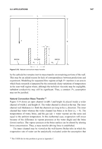
Figure 5.19. Natural convection mass transfer.
by the cathode but remains inert to mass transfer on remaining portions of the wall.
This may be an added reason for lack of correspondence between predictions and
experiment. Modelling for separated flow regions at high Pr numbers is an area in
which basic research is hampered by the extremely sharp variations of temperature
in the near-wall region where, although the turbulent viscosity may be negligible,
turbulent conductivity may still be significant. Thus, a constant Pr t assumption
may not be justified.
Natural Convection Mass Transfer 19
Figure 5.19 shows an open channel (width l and height h) placed inside a wider
channel of width L and height H. The wider channel is closed at the top. The inner
channel wall thickness is t. Both the channels are long in the x 3 direction. The inner
channel has water whereas the wider channel has brine at its floor (x 2 = 0). The
temperatures of water, brine, and the gas (air + water vapour) are the same and
equal to the ambient temperature. In this isothermal case, evaporation will ensue
because of the difference in vapour pressures at the water (high) and the brine
(lower) surface. The vapour pressure at the brine surface can be altered by altering
brine concentration. Thus, a mass transfer driving force is established.
The inner channel may be viewed as the well-known Stefan tube in which the
evaporation rate of water can be analytically evaluated under the assumption that
19 The USER file for this problem is given in Appendix C.