
Page 125 - Introduction to Mineral Exploration
P. 125
108 M.K.G. WHATELEY
(a) VISIBLE
GAMMA X - RAY ULTRA-VIOLET INFRARED MICROWAVE RADIO
RAY
Expanded
figure (b)
SIR A & B
Reflected IR Thermal IR (typical)
Seasat
Aircraft
10 –12 10 –11 10 –10 10 –9 10 –8 10 –7 10 –6 10 –5 10 –4 10 –3 10 –2 10 –1 10 0 10 1
Wavelength 1 nm 1 mm 1mm 1 cm 1m
(b) ULTRA -
VISIBLE INFRARED
VIOLET
Reflected IR Thermal IR
O 3 H O H O CO 2 CO 2 H O O 3 CO 2
2
2
2
100 H O
2
80
Atmospheric transmission % 60 Photo. UV Photo. IR
40
20
0 Blue Green Red 1.6 µm 2.2 µm 3–5 µm 8–14 µm
0.5 1.0 1.5 2.0 3.0 4.0 5.0 10 15 20 30
Wavelength (mm)
Normal color photos Aircraft
IR scanners
IR color photos
Satellite
4 5 6 7 Landsat multispectral scanner IR scanners
IMAGING
SYSTEMS 12 3 4 5 7 Landsat thematic mapper 6
1 2 3 4 5–9 Aster 10–12 13–14
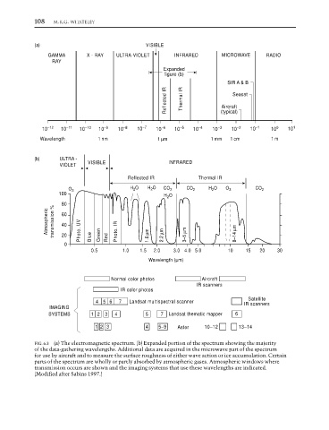
FIG. 6.3 (a) The electromagnetic spectrum. (b) Expanded portion of the spectrum showing the majority
of the data-gathering wavelengths. Additional data are acquired in the microwave part of the spectrum
for use by aircraft and to measure the surface roughness of either wave action or ice accumulation. Certain
parts of the spectrum are wholly or partly absorbed by atmospheric gases. Atmospheric windows where
transmission occurs are shown and the imaging systems that use these wavelengths are indicated.
(Modified after Sabins 1997.)