
Page 126 - Introduction to Mineral Exploration
P. 126
6: REMOTE SENSING 109
transmitted to earth for storage on Computer ness, of that very small area within the scene.
Compatible Tapes (CCTs). These tapes are then Satellite scanners look through the atmosphere
processed on a computer to produce images. at the earth’s surface, and the sensor therefore
The width of scene dimensions on the surface measures the reflected radiation from the sur-
under the satellite (its swath) is 185 km. The face and radiation scattered by the atmosphere.
data are (for convenience) divided into sets that The pixel value represents both. Fortunately,
equal 185 km along its path. the level of scattered radiation is nearly con-
The satellites have a polar, sun synchronous stant, so changes in pixel value are essenti-
orbit, and the scanners only record on the ally caused by changes in the radiance of the
southbound path (Fig. 6.2) because it is night- surface.
time on the northbound path. The paths of The Instantaneous Field of View (IFOV) is
Landsats 1 to 3 shifted west by 160 km at the the distance between consecutive measure-
equator each day so that every 18 days the ments of pixel radiance (79 m × 79 m in MSS),
paths repeat resulting in repetitive, worldwide, which is commonly the same as the pixel size
MSS coverage. Landsats 4, 5 and 7 and the Terra (Table 6.1). However, MSS scan lines overlap,
satellite have a slightly different orbit result- hence the pixel interval is less than the IFOV
ing in a revisit frequency of 16 days. Images (56 m × 79 m). The TM and ASTER detectors
are collected at the same local time on each have a greatly improved spatial resolution,
pass – generally between 9.30 and 10.30 a.m. giving an IFOV of 30 m × 30 m.
to ensure similar illumination conditions on The radiance for each pixel is quantified into
adjacent tracks. Successive paths overlap by discrete gray levels and a finite number of bits
34% at 40°N and 14% at the equator. Landsat are used to represent these data (Table 6.2).
does not give stereoscopic coverage, although Table 6.2 shows how decimal numbers in the
it can be added digitally. ASTER does give range 0–255 can be coded using eight indi-
stereoscopic coverage. vidual bits (0 or 1) of data. Each is grouped as an
8 bit “byte” of information, with each bit used
0
to indicate ascending powers of 2 from 2 (=1) to
6.2.2 Pixel parameters 7
2 (=128). This scheme enables us to code just
Digital images consist of discrete picture ele- 256 (0–255) values. On the display terminal,
ments, or pixels. Associated with each pixel is 256 different brightness levels are used, cor-
a number that is the average radiance, or bright- responding to different shades of gray ranging
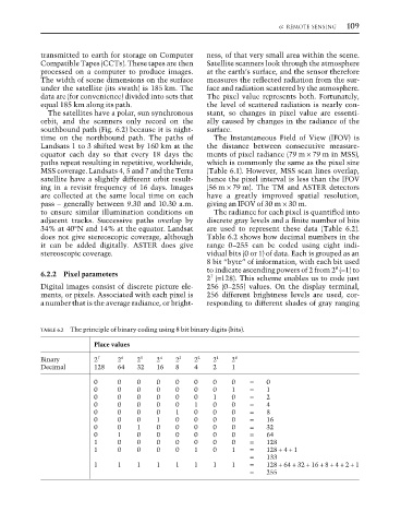
TABLE 6.2 The principle of binary coding using 8 bit binary digits (bits).
Place values
Binary 2 7 2 6 2 5 2 4 2 3 2 2 2 1 2 0
Decimal 128 64 32 16 8 4 2 1
0 0 0 0 0 0 0 0 = 0
0 0 0 0 0 0 0 1 = 1
0 0 0 0 0 0 1 0 = 2
0 0 0 0 0 1 0 0 = 4
0 0 0 0 1 0 0 0 = 8
0 0 0 1 0 0 0 0 = 16
0 0 1 0 0 0 0 0 = 32
0 1 0 0 0 0 0 0 = 64
1 0 0 0 0 0 0 0 = 128
1 0 0 0 0 1 0 1 = 128 + 4 + 1
= 133
1 1 1 1 1 1 1 1 = 128 + 64 + 32 + 16 + 8 + 4 + 2 + 1
= 255