
Page 230 - Introduction to Mineral Exploration
P. 230
10: EVALUATION TECHNIQUES 213
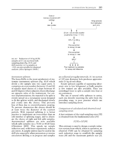
Core or
reverse circulation drill
cuttings
18 kg samples
from bulk plant
Jaw crusher (at 5 mm)
23 cm × 23 cm rolls crusher
(crushed to minus 1.7 mm)
SPLIT to 450 g
Disc pulverizer
to minus 0.4 mm
Disc pulverizer
to minus 0.1 mm
FIG. 10.7 Reduction of 18 kg (40 lb) SPLIT
samples at 0.5 cm size from bulk
sampling plant (Fig. 10.5), and
drill material, to 5 g samples at
−0.01 cm size suitable for chemical Four replicate 5 g samples
analysis. (After Springett 1983b.) for assay and reference
Instrument splitters are collected at regular intervals. A 1 m section
The Jones Riffle is the most satisfactory of sta- of 102 mm diameter hole produces approxim-
tionary instrument splitters (Fig. 10.8) which ately 21 kg of rock chips.
divide a dry sample into two equal parts. It Rotary splitters capable of separating labor-
comprises an even number (between 12 and 20) atory size (a few kilograms) or bulk samples
of equally sized chutes of a slope between 45 (a few tonnes) are also available. They use
and 60 degrees where adjacent chutes discharge centrifugal force to split a sample into four or
on opposite sides of the instrument. For cor- six containers.
rect implementation, the material to be split is The use of several riffle splitters in series,
evenly spread on a rectangular scoop designed each one directly receiving the split from the
to fit the splitter width, and discharged slowly preceding stage, is poor practice which can
and evenly into the chutes. This prevents introduce sampling errors.
loss of fines due to overenthusiastic pouring.
To prevent obstruction the chutes should be
at least twice the diameter of the coarsest Comparison of calculated and observed total
particle. With repeated splitting it is better sampling errors
practice to implement an even rather than an A best estimate of the total sampling error (TE)
odd number of splitting stages, and to altern- is obtained from the fundamental error (FE):
ate the choice of right and left split samples.
2
2
Asymmetrical splitters are now available S (TE) = 2S (FE)
which split samples on a 70:30 or 80:20 basis
(Christison 2002). This speeds up sample This estimate is used to design a sample reduc-
reduction and, with fewer separations, reduces tion system from which, when in operation, an
2
any errors. A sample splitter may be used at the observed S (FE) can be obtained by sampling
drill site especially when percussion or reverse each reduction stage to establish the sample
circulation drilling is in progress and samples mass (M) and the maximum particle size (d),