
Page 263 - Introduction to Mineral Exploration
P. 263
246 M.K.G. WHATELEY & B. SCOTT
Load Axial stress
(a) σ (b) σ 1
σ 1
Seal Shear fracture
Steel σ
σ n
cylinder
θ
σ
σ
σ
σ
σ σ Borehole core σ 2 =σ 3 τ σ 2 =σ 3
σ 2 =σ 3
Confining Confining
pressure pressure
Flexible membrane
Fluid filled
chamber
Pressure from pump
σ 2
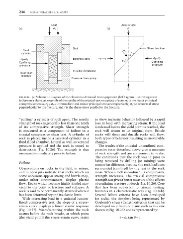
FIG. 10.26 (a) Schematic diagram of the elements of triaxial test equipment. (b) Diagram illustrating shear
failure on a plane, an example of the results of the triaxial test on a piece of core. σ 1 is the major principal
compressive stress, σ 2 = σ 3 = intermediate and minor principal stresses respectively, σ n is the normal stress
perpendicular to the fracture, and τ is the shear stress parallel to the fracture.
“pulling” a cylinder of rock apart. The tensile to show inelastic behavior followed by a rapid
strength of rock is generally less than one tenth loss in load with increasing strain. If the load
of its compressive strength. Shear strength is released before the yield point is reached, the
is measured as a component of failure in a rock will return to its original form. Brittle
triaxial compressive shear test. A cylinder of rocks will shear and ductile rocks will flow,
rock is placed inside a jacketed cylinder in a both types of behavior resulting in irreversible
fluid-filled chamber. Lateral as well as vertical changes.
pressure is applied and the rock is tested to The results of the uniaxial (unconfined) com-
destruction (Fig. 10.26). The strength is that pressive tests described above give a measure
measured immediately prior to failure. of rock strength and are convenient to make.
The conditions that the rock was in prior to
being removed by drilling (or mining) were
Failure
somewhat different, because the rock had been
Observations on rocks in the field, in mines, surrounded (confined) by the rest of the rock
and in open pits indicate that rocks which on mass. When a rock is confined its compressive
some occasions appear strong and brittle may, strength increases. The triaxial compressive
under other circumstances, display plastic strength test gives a better measure of the effects
flow. Rocks which become highly loaded may of confining pressure at depth (Fig. 10.26). Core
yield to the point of fracture and collapse. A that has been subjected to triaxial testing,
rock is said to be permanently strained when it fractures in a characteristic way (Fig. 10.26b).
has been deformed beyond its elastic limit. Several failure criteria have been developed
With increasing load in a uniaxial (uncon- for rocks, the simplest being represented by
fined) compressive test, the slope of a stress– Coulomb’s shear strength criterion that can be
strain curve displays a linear elastic response developed on a fracture plane such as the one
(Fig. 10.27). Microfracturing within the rock shown in Fig. 10.26b and is represented by:
occurs before the rock breaks, at which point
(the yield point) the stress–strain curve starts τ = σ n tan θ + c