
Page 192 - System on Package_ Miniaturization of the Entire System
P. 192
166 Cha pte r F o u r
Port 1
Port 1
Top electrode
HL1
LCP
Bottom electrode
VL1
Port 2
Prepreg
Ground plane
Port 2
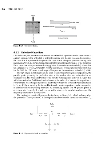
FIGURE 4.10 Capacitor layout.
4.2.2 Embedded Capacitors
Like inductors, the parameters of interest for embedded capacitors are its capacitance at
a given frequency, the unloaded Q at that frequency, and the self-resonant frequency of
the capacitor. It is preferable to operate the capacitor at a frequency corresponding to its
maximum Q. Both the conductor and dielectric loss affect the performance of the capacitor.
For a capacitor with perfect conducting plates, the maximum unloaded Q achievable
for a capacitor is 1/tan d, where tan d is the loss tangent of the dielectric material. Since
tan d = 0.002 for LCP over a broad range of frequencies, the maximum unloaded Q is 500.
Though single metal layers can be used to construct interdigitated capacitors, the
parallel plate geometry is preferable due to its smaller size and minimization of
conductor loss. The physical structure of the parallel plate capacitor is shown in Figure 4.10
with two electrodes. Additional electrodes can be introduced to increase the capacitance.
For example, by adding an additional electrode between the top and bottom electrodes
in Figure 4.10 and shorting the top and bottom electrodes, capacitors can be constructed
in parallel without increasing area (but by increasing layers). The RF ground plane is
also shown in Figure 4.10, which is used as the reference to simulate and measure the
frequency response of the capacitor.
The equivalent circuit of the capacitor is shown in Figure 4.11, which includes all of
the parasitics. The capacitor C is the capacitance between the capacitor electrodes, C p1
S
R s 1 a
C s
Port 1 Port 2
L s 1 R s 1 R s 2 L s 2
C p 1 C p 2
FIGURE 4.11 Equivalent circuit of capacitor.