
Page 197 - System on Package_ Miniaturization of the Entire System
P. 197
Mixed-Signal (SOP) Design 171
filter in the stopbands at 0.5 GHz. From the plots it can be seen that in the stopbands the
circuit functions as a short circuit wherein the majority of current is directed through
the resonator inductors to ground. Hence, high-Q inductors are required to improve
insertion loss and minimize excessive heating, especially in high-power applications.
As shown in Figure 4.15, careful modeling of the structure can provide an excellent
model-to-hardware correlation. However, not all structures can be modeled using
electromagnetic simulators, especially when many more components are integrated,
due to enormously large simulation time. Hence, an intermediate step using circuit-
level simulation becomes necessary during the design phase that enables rapid changes
to the layout, based on performance evaluations. This can be followed by the modeling
of an entire layout, which may take a day to complete.
The filter can be scaled in frequency by scaling the resonator network. Addition of
transmission zeros is possible by adding a feedback capacitor between input and output
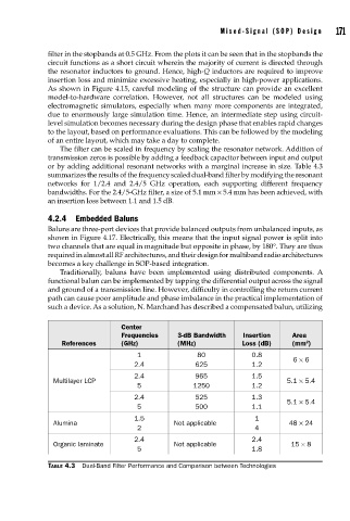
or by adding additional resonant networks with a marginal increase in size. Table 4.3
summarizes the results of the frequency scaled dual-band filter by modifying the resonant
networks for 1/2.4 and 2.4/5 GHz operation, each supporting different frequency
bandwidths. For the 2.4/5-GHz filter, a size of 5.1 mm × 5.4 mm has been achieved, with
an insertion loss between 1.1 and 1.5 dB.
4.2.4 Embedded Baluns
Baluns are three-port devices that provide balanced outputs from unbalanced inputs, as
shown in Figure 4.17. Electrically, this means that the input signal power is split into
two channels that are equal in magnitude but opposite in phase, by 180°. They are thus
required in almost all RF architectures, and their design for multiband radio architectures
becomes a key challenge in SOP-based integration.
Traditionally, baluns have been implemented using distributed components. A
functional balun can be implemented by tapping the differential output across the signal
and ground of a transmission line. However, difficulty in controlling the return current
path can cause poor amplitude and phase imbalance in the practical implementation of
such a device. As a solution, N. Marchand has described a compensated balun, utilizing
Center
Frequencies 3-dB Bandwidth Insertion Area
2
References (GHz) (MHz) Loss (dB) (mm )
1 80 0.8
6 × 6
2.4 625 1.2
2.4 965 1.5
Multilayer LCP 5.1 × 5.4
5 1250 1.2
2.4 525 1.3
5.1 × 5.4
5 500 1.1
1.5 1
Alumina Not applicable 48 × 24
2 4
2.4 2.4
Organic laminate Not applicable 15 × 8
5 1.8
TABLE 4.3 Dual-Band Filter Performance and Comparison between Technologies