
Page 198 - System on Package_ Miniaturization of the Entire System
P. 198
172 Cha pte r F o u r
Input Outputs
FIGURE 4.17 Functional representation of a balun.
a second transmission line segment with the same electrical properties as the first one
to compensate for the effect of the reference ground and thus match the output signals
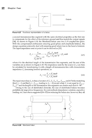
[34]. As shown in Figure 4.18, the Marchand balun uses two λ/4 coupled-line pairs.
With the compensated architecture ensuring good phase and amplitude balance, the
design equations primarily deal with ensuring good return loss in the band of interest.
The input impedance seen at point d can be derived as [35]
Z jZ 2 Z tanθ
Z = load + load ab − jZ cotθ
d 2 2 + Z tan θ b (4.5)
2
2
Z Z
load + 1 loaad ab
Z tan θ
2
2
ab
where q is the electrical length of the transmission line segments, and the rest of the
variables are as shown in Figure 4.18. The impedance seen by the source (Z ) can then
in
be calculated by transforming Z with a length of transmission line with characteristic
d
impedance Z (assuming lossless operation), as
a
Z + jZ tanθ
Z = Z d a (4.6)
in a Z + jZ tanθ
a d
The input return loss S is thus a function of Z , Z , Z , Z load , Z source , and q. Perfect matching
11
a
ab
b
[Im(Z ) = 0 and Re(Z ) = Z , leading to S = 0] occurs when Z is set equal to (Z .
in in source 11 a source
Z load ) and the lengths of the transmission line segments are chosen such that q = 90°.
1/2
Owing to the use of distributed elements, the size of distributed baluns becomes
prohibitively large at low frequencies. Several methods (impedance variation, capacitive
loading, etc.) have been suggested [36–37] for reducing the balun size; however, they all
Z ab
d
Z in
Z load
Z a
FIGURE 4.18 Marchand balun.