
Page 202 - System on Package_ Miniaturization of the Entire System
P. 202
176 Cha pte r F o u r
Antenna Filter Balun LNA
FIGURE 4.23 Filter-balun in a receiver front end.
in the substrate can be used that combines the functionality of both a balun and a filter.
Any single-ended circuit can be made into a balanced network (with differential inputs
and differential outputs) using network theory [40]. Balanced bandpass filters can
also be designed in this fashion. However, this technique also results in an increase in
the number of components. It leads to doubling of the capacitance values required in
the series path [40], which can lead to large device sizes in embedded circuits where the
device size is directly proportional to the capacitance or inductance value required.
Lattice filters have also been used in the past to achieve balanced filter topologies
[41–42]. Although they provide both frequency selectivity and differential outputs, both
these approaches require additional matching circuits for single-ended to differential
conversion at the input port. Two alternate approaches are adding frequency selectivity
to existing balun circuits and cascading a balun with a bandpass filter.
The Marchand balun by its very nature has a bandpass behavior. The coupled line
segments prevent the transmission of signals at low frequencies, while the transmission
line behavior causes the signal transmission to fall off after the resonant frequency of
the coupled lines. Implementation of the lumped elements in the modified Marchand
balun using resonators allows transmission zeroes in the transfer function of the balun,
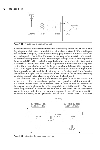
leading to sharper roll-offs for the frequency response. Figure 4.24 shows a modified
Marchand balun designed for operation in the 5- to 6-GHz frequency band. To increase
Z e = 120Ω, Z o = 22Ω Z e = 120Ω, Z o = 22Ω
θ = 90°, f = 14 GHz θ = 90°, f = 14 GHz
0.72 nH
0.65 nH 0.65 nH
0.13 pF
0.45 pF
FIGURE 4.24 Integrated Marchand balun and fi lter.