
Page 199 - System on Package_ Miniaturization of the Entire System
P. 199
Mixed-Signal (SOP) Design 173
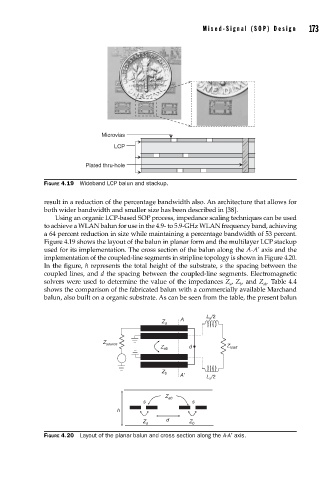
Microvias
LCP
Plated thru-hole
FIGURE 4.19 Wideband LCP balun and stackup.
result in a reduction of the percentage bandwidth also. An architecture that allows for
both wider bandwidth and smaller size has been described in [38].
Using an organic LCP-based SOP process, impedance scaling techniques can be used
to achieve a WLAN balun for use in the 4.9- to 5.9-GHz WLAN frequency band, achieving
a 64 percent reduction in size while maintaining a percentage bandwidth of 53 percent.
Figure 4.19 shows the layout of the balun in planar form and the multilayer LCP stackup
used for its implementation. The cross section of the balun along the A-A’ axis and the
implementation of the coupled-line segments in stripline topology is shown in Figure 4.20.
In the figure, h represents the total height of the substrate, s the spacing between the
coupled lines, and d the spacing between the coupled-line segments. Electromagnetic
solvers were used to determine the value of the impedances Z , Z , and Z . Table 4.4
a b ab
shows the comparison of the fabricated balun with a commercially available Marchand
balun, also built on a organic substrate. As can be seen from the table, the present balun
L x /2
A
Z a
Z source
d
Z ab Z load
Z b
A’ L x /2
Z ab
s s
h
d
Z a Z b
FIGURE 4.20 Layout of the planar balun and cross section along the A-A′ axis.