
Page 184 - Sami Franssila Introduction to Microfabrication
P. 184
Ion Implantation 163
The scaling down of ion energy involves a number of can be fooled by similar ion masses, termed mass
techniques. One of the oldest techniques is to implant contamination. Doubly charged molybdenum ions Mo +2
+ +
molecular ions instead of ions: BF 2 has a mass of can pass along with BF 2 ions (molybdenum is a
49 versus 11 for that of boron, and its range is ca. common construction material for vacuum equipment).
a fifth of the boron range in the first approximation. 11 BHF + ion behaves like a 31 + ion for the selection
P
The replacement of B for BF + is not straightforward, magnet. This situation might emerge when PH 3 gas is
2
however, because the behaviour of fluorine during used after BF 3 gas and some residual gas remains in
annealing and further processing needs to be accounted the ion source. Energy purity refers to the spread of
for. True low energy implanters must accept the fact ion energies in the beam, and consequently, their range
that a lower beam current is available. In the limit in silicon.
of 1 keV, the sputtering of the surface atoms becomes The acceleration tube must be kept under high vac-
important: because the low implant energy equals the uum in order to steer the beam to the wafer in a collision-
low penetration depth and every atom layer removed less fashion. After acceleration, either electromagnetic
from the surface will affect the final implant profile. or mechanical scanning spreads the beam over the wafer.
Implantation is an inherently slow process because of the
15.4.1 Implanter design and operation scanning nature of the operation. Alternative implanta-
tion techniques that work in parallel mode have been
Implantation requires ions, and these are generated in devised: plasma immersion ion implantation (PIII) is
ion sources that are plasma discharges. The dopants a process in which the wafer is immersed in plasma,
have to be vapourized or be in the gaseous state before and biased. Very high-dose rates are possible, but the
ionization. The dopant gases in routine use are PH 3 , energy purity is sacrificed because the selection magnet
AsH 3 and BF 3 , but evaporation of solids in a furnace has been eliminated from the system. A PIII may have
can also be used, and almost all elements in the periodic applications in large-area applications like flat-panel dis-
table can be implanted. However, efficiency of the solid
plays because of its high throughput.
sources is low and switching between the ions is slow.
The wafers will be charged when ions are implanted.
The ions are extracted from the source by voltage, and
The current flows from the beam to the wafer holder,
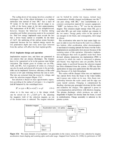
enter the selection magnet (Figure 15.6). and it passes any oxides on its way. Also, beam non-
Ion selection is based on mass spectrometric separa- uniformity between the wafer centre and the edge can
tion according to the radius of curvature r in a magnetic cause lateral currents. Charging is compensated by
field B balanced by the centrifugal force:
flooding: electron gun generated electrons hit the wafer
2 and neutralize the charges. This approach is prone to
|F| = |q(v × B)| = m|v| /r = qV (15.4)
overcompensation and problems with electron charging.
where m is the mass and q is the charge which The plasma discharge, which produces an order of
2
can be solved for B = (2mV /qr ). By adjusting magnitude of higher ion density than the beam, is used
the magnetic field of the selection magnet, an ion in neutralization. Charge neutrality is inherent in the
of the desired mass is selected. The magnet selection plasma system.
Selection magnet Wafer
Acceleration tube Ion optics chamber
Faraday
cup
Load
Extraction lock
Ion source Gas 1
Gas 2
Figure 15.6 The main elements of an implanter: ion generation in the source, extraction of ions, selection by magnet,
acceleration, beam shaping and scanning optics and wafer stage. Adapted from Current, M. (1996), by permission of AIP