
Page 351 - Sami Franssila Introduction to Microfabrication
P. 351
330 Introduction to Microfabrication
1. transport-limited deposition, k s ≫ h g ; If we lower the operating pressure by a factor of 1000,
C s = (h g /k s )C g ; diffusivity increases thousand-fold because D changes
2. surface reaction-limited deposition, k s ≪ h g ; as a function of pressure and temperature roughly as
C s = C g .
D ∝ T 3/2 /P (33.6)
In the former, the reaction rate at the surface is very
high and leads to local depletion of reactants. Supply There is an opposing trend of boundary-layer thickness
increase because density decreases and flow velocity
of reactants by the gas flow or their diffusion through
increases, but because of square root dependence
the boundary layer is then the rate-limiting step. In the
(Equation 33.5), this opposing trend is ca. one order of
latter case, an oversupply of reactants is brought to the
magnitude only. Diffusivity increase clearly dominates,
vicinity of the surface, but the surface reaction cannot
consume all of them. and gas-phase transport of reactants to the surface is
The gas-phase transport coefficient h g , can be gauged greatly enhanced. A reaction that was transport-limited
as follows: in Fick’s law J = −D(dC/dx) we identify at higher pressure can be turned to surface reaction
(dx) with the boundary layer thickness δ and get controlled, by operating at reduced pressure.
In order to get a feeling for temperature dependence,
J gas-to-surface = −(D/δ)C g (33.4) we have to compare k s and h g as a function of tem-
perature. Chemical reactions obey Arrhenius behaviour
Boundary layer is the region of fluid where wall friction with exponential dependence, and thus, surface reaction-
is important. Boundary-layer thickness δ is given by limited deposition is strongly temperature dependent
(high E a ). The gas-phase transport coefficient h g is pro-
1/2
δ = (ηL/vρ) (33.5) portional to D, which has T 3/2 temperature dependence.
This explains the shallower slope in the transport-limited
where η is viscosity, v is fluid velocity, ρ is its density
regime of Figure 5.6.
and L is the characteristic dimension of the system.
Boundary-layer thickness increases along the flow and
is thicker in the exhaust end of the reactor compared 33.2 CVD REACTORS
with the inlet end.
◦
For atmospheric system at ca. 1000 C, the values APCVD reactors operate in a transport-limited mode
2
are D ≈ 10 cm /s, L ≈ 100 cm, η ≈ 10 −4 poise (g/cm- and flow geometries are important for film unifor-
3
s) and ρ ≈ 10 −4 g/cm (ρ ∝ (1/T )) we get an approx- mity. LPCVD reactors operate in a surface reaction-
imate boundary-layer thickness of 3 cm, which is close controlled regime and wafers can be packed closely,
to values found in real systems. Gas-phase transfer coef- which increases system throughput. LPCVD reactors
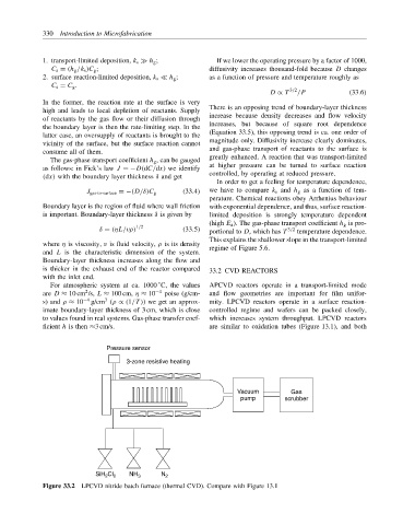
ficient h is then ≈3 cm/s. are similar to oxidation tubes (Figure 13.1), and both
Pressure sensor
3-zone resistive heating
Vacuum Gas
pump scrubber
SiH Cl 2 NH 3 N 2
2
Figure 33.2 LPCVD nitride batch furnace (thermal CVD). Compare with Figure 13.1