
Page 355 - Sami Franssila Introduction to Microfabrication
P. 355
334 Introduction to Microfabrication
ranges but practically identical activation energies in the reactors typically have ca. 1 µm/min growth rates, and
surface reaction limited regime. Most epitaxy reactors, they are preferred for thick-layer applications (up to
however, operate in the transport-limited regime, and 200 µm in some power devices) in which interface
gas-flow design in the reactor is crucial. sharpness is not an issue. Batch-loading reactors can
Epitaxy is not necessarily a high-temperature process. take, for instance, 30 wafers of 100 mm diameter or 12
It has traditionally been so, but epitaxy as such can wafers of 200 mm diameter.
be carried out at any temperature. In situ cleaning of Single-wafer reactors offer high growth rates, for
the wafer has been a factor for high temperatures: HCl example, 5 µm/min at 1120 C, using trichlorosilane. In
◦
or H 2 gas-phase cleaning processes worked better at addition to steep interface due to short deposition time,
elevated temperatures. Surface composition, however, single-wafer reactors are superior with respect to film
is also dependent on the preceding cleaning step, and uniformity: 1% across the wafer for thickness, 4% for
if that can be modified to reduce native oxide growth, resistivity. Rotating susceptor, which comes naturally in
in situ cleaning temperature can be lowered. a single-wafer reactor, is responsible for the uniformity,
and also for a wider operating window because gas-
flow rate, velocity and boundary-layer thickness can be
33.6 EPITAXIAL REACTORS
varied over a wider range. A thinner boundary layer,
for example, means that evaporated dopants from buried
Reactors can be classified according to gas-flow pat-
layers will rapidly diffuse to the main gas flow and be
terns: gas flow parallel to the wafer surface is used in
swept away.
barrel (aka hexode) reactors where the wafers are verti-
cally placed, and also in single-wafer reactors where the Epi reactors operate either at atmospheric pressure
wafer is horizontally placed. In vertical reactors, wafers but reduced pressure, typically 50 to 100 torr, can also
are flat on a susceptor but gases flow vertically perpen- be used. Reduced pressure operation adds to equipment
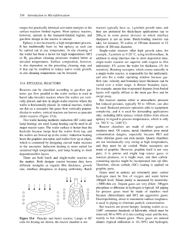
dicular to wafers; vertical reactors are known as pancake complexity, and it is used for demanding applications
(disk) reactors (Figure 33.6). only, including SiGe epitaxy (which differs from silicon
Two wafer heating methods; induction (RF coils) and epitaxy in regard to process temperatures, which is only
◦
◦
lamp heating; are used. Lamp heating can be used in all ca. 700 C vs. 1100 C).
major reactor types. The wafer surface is hotter than the Reactor chambers are made of either quartz or
backside because lamps heat the wafers from top, and stainless steel. Of course, metal chambers pose metal
the wafers are bowed up at the centre. Induction heating contamination dangers, especially because HCl and
heats the graphite susceptor, and wafers bow up at edges, other chlorine gases can etch metals. Quartz chambers
which is countered by designing curved wafer recesses are not mechanically very strong at high temperatures,
in the susceptor. Induction heating is more suited for and they must be air cooled. Wafer susceptors are
sustained high temperatures, and lamp heating to short made of graphite. However, graphite itself is not very
depositions/thin layers. pure; it is porous and might trap source gases or
There are both batch and single-wafer reactors on reaction products, or it might react, and then carbon-
the market. Both designs coexist because they have containing species might be incorporated into epi film.
different strengths as regards film thickness, growth Therefore, silicon carbide (SiC) coating is applied on
rate, interface abruptness or doping uniformity. Batch graphite parts.
Gases used in epitaxy are extremely pure: carrier
hydrogen must be free of oxygen and water below
100 ppb level. Silane purity is measured by resistivity:
>3000 ohm-cm. Dopant gases are very dilute: 100 ppm
phosphine or diborane in hydrogen is typical. All piping
for process gases must be made of stainless steel
because chlorosilanes and HCl are aggressive gases.
Electropolishing, down to nanometre-surface roughness,
is used in piping to eliminate particle contamination.
Epi reactors are power hungry: keeping wafers at ca.
1100 consumes hundreds of kilowatts, which must be
◦
removed: 80 to 90% of it into cooling water and the rest,
Figure 33.6 Pancake and barrel reactors. Lamps or RF mainly to hot exhaust gases. These gases are unused
coils for heating are shown, the reactor chamber is not silanes (typical utilization is 10–30%) and hydrogen,