
Page 220 - Low Temperature Energy Systems with Applications of Renewable Energy
P. 220
Heating with geothermal systems 207
Systems using working fluids with high heat capacity of saturated liquid are more
effective. The installation of the regenerative heat exchanger ensures “dry running” of
the compressor, i.e., superheated vapor at the compressor inlet, and an increase in the
specific cooling capacity. The COP for a refrigerator with a regenerative heat
exchanger is determined by the formula:
q 0 þ Dq 0
COP ¼ (5.3)
w þ Dw
where, Dw ¼ w 2 w 1 , is the increment of the compressor power in the scheme with
the regenerator (w 2 ), and without the regenerator (w 1 ); Dw arises from the divergence
of isobars as the temperature is raised.
If Dq 0 < Dw, then the cycle with the regenerative heat exchanger is less efficient.
Even if the COP is not improved, the regenerative heat exchanger provides for a dry
compression process which is more effective and practical than a wet one.
An economizer EC installed after the condenser, also provides liquid subcooling
before throttling (Fig. 5.31). However, the economizer does not guarantee a dry
compression process. The subcooling in the economizer, process (4e6), before throt-
tling (6e1) is carried out at the expense of part of the useful cooling capacity.
The specific cooling capacity q 0 * obtained in the process 5-2 is internal to the cy-
00
cle, whereas the specific cooling capacity q 0 in the process 1-2 is the beneficial effect
0
of the refrigerator. The maximum increase in specific cooling capacity by subcooling
the working substance before throttling is Dq 0 ¼ h 4 h 6 .
The heat balance of the economizer EC is determined by the formula:
ð _ m 4 _ m 5 Þðh 4 h 6 Þ¼ _ m 5 ðh 2} h 5 Þ (5.4)
where _ m 5 is the liquid flow rate bled from state 4 and sent to the first throttle valve
TV1. If the mass flow through the compressor is defined as unity, i.e., _ m 4 h 1, then we
find
_ m 5
h 6 h 4 ¼ ðh 5 h 2} Þ (5.4a)
1 _ m 5
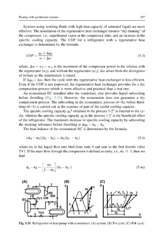
Fig. 5.31 Refrigerator or heat pump with economizer: (A) system; (B) T-s cycle; (C) P-h cycle.