
Page 219 - Low Temperature Energy Systems with Applications of Renewable Energy
P. 219
206 Low-Temperature Energy Systems with Applications of Renewable Energy
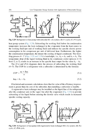
Fig. 5.29 Refrigerator or heat pump with subcooler SC: (A) system; (B) T-s cycle; (C) P-h cycle.
heat pump system (Fig. 5.29). Subcooling the working fluid below the condensation
temperature increases the heat exchanged in the evaporator from the heat source to
the working fluid (per unit of working fluid) and reduces the specific electric power
consumption in the compressor per unit of delivered heat. Furthermore, the higher
the condensation temperature, the deeper the cooling of liquid condensate. The throt-
0
tling process 4 1 (Figs. 5.29 and 5.30) is isenthalpic, i.e., h 4 ¼ h 1 and h 5 ¼ h 1 . The
0
temperature drop of the liquid working fluid in the condensate cooler (process 4e5)
from T c to T 5 results in an increase in the specific heat output for the value h 4 h 5 .
The (T,s) and (P,h) diagrams show the process of subcooling the working fluid
(4e5). The COP for a refrigerator with a subcooler is determined by the formula:
q 0 þ Dq 0
COP ¼ (5.1)
w
Dq 0 ¼ h 4 h 5 (5.2)
If technical and economic calculations show that the value of the efficiency improve-
ment is greater than the cost of the subcooler, then installing a subcooler is feasible.
A regenerative heat exchanger may be installed on the liquid line of the refrigerant
after the condenser and on the vapor line after the evaporator (Fig. 5.30) to provide
subcooling of the liquid before entering the throttle valve which results in increased
specific cooling capacity.
Fig. 5.30 Refrigerator or heat pump with regenerative heat exchanger RH: (A) system; (B) T-s
cycle; (C) P-h cycle.