
Page 126 - Make Your Own PCBs with EAGLE from Schematic Designs to Finished Boards
P. 126
The design rule checker (DRC) is to the Board Editor what the ERC is to the Schematic Editor. It
performs all sorts of checks that make sure that tracks are not crossing each other on the same layer,
located too close together, and so on.
Because the design rules are complicated to set up, you can load and save sets of design rules and
even download sets of design rules that others, such as Sparkfun, have made available to everyone.
The Grid
The schematic is drawn on a grid, which helps you to lay things out neatly by allowing you to snap
parts and net lines to the nearest point on the grid. However, the grid is much more important for
board design.
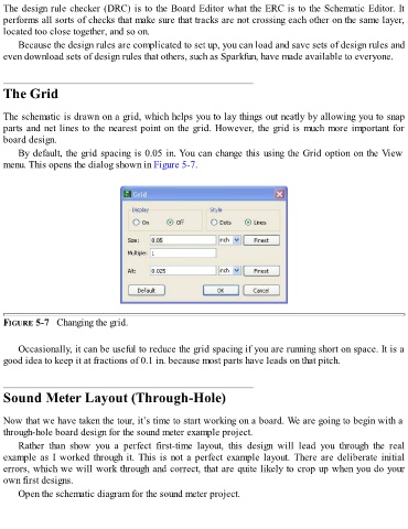
By default, the grid spacing is 0.05 in. You can change this using the Grid option on the View
menu. This opens the dialog shown in Figure 5-7.
FIGURE 5-7 Changing the grid.
Occasionally, it can be useful to reduce the grid spacing if you are running short on space. It is a
good idea to keep it at fractions of 0.1 in. because most parts have leads on that pitch.
Sound Meter Layout (Through-Hole)
Now that we have taken the tour, it’s time to start working on a board. We are going to begin with a
through-hole board design for the sound meter example project.
Rather than show you a perfect first-time layout, this design will lead you through the real
example as I worked through it. This is not a perfect example layout. There are deliberate initial
errors, which we will work through and correct, that are quite likely to crop up when you do your
own first designs.
Open the schematic diagram for the sound meter project.