
Page 661 - Manufacturing Engineering and Technology - Kalpakjian, Serope : Schmid, Steven R.
P. 661
642 Chapter 23 Machining Processes: Turning and Hole Making
Steel or
|r1SerT carbide shank Coolant Tungsten-alloy disks
M Il -1
(H) (D)
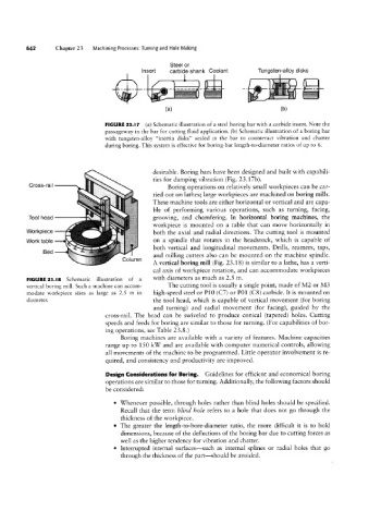
FIGURE 23.I1 (a) Schematic illustration of a steel boring bar with a carbide insert. Note the
passageway in the bar for cutting fluid application. (b) Schematic illustration of a boring bar
with tungsten-alloy “inertia disks” sealed in the bar to counteract vibration and chatter
during boring. This system is effective for boring-bar length-to-diameter ratios of up to 6.
desirable. Boring bars have been designed and built with capabili-
ties for damping vibration (Fig. 23.17b).
Cross-rail Boring operations on relatively small workpieces can be car-
ried out on lathes; large workpieces are machined on boring mills.
These machine tools are either horizontal or vertical and are capa-
ble of performing various operations, such as turning, facing,
Tool head grooving, and chamfering. In horizontal boring machines, the
workpiece is mounted on a table that can move horizontally in
Workpiece both the axial and radial directions. The cutting tool is mounted
Work table on a spindle that rotates in the headstock, which is capable of
both vertical and longitudinal movements. Drills, reamers, taps,
Bed
and milling cutters also can be mounted on the machine spindle.
Column
A vertical boring mill (Fig. 23.18) is similar to a lathe, has a verti-
cal axis of workpiece rotation, and can accommodate workpieces
FIGURE 23.|8 Schematic illustration of a with diameters as much as 2.5 m.
vertical boring mill. Such a machine can accom- The cutting tool is usually a single point, made of M2 or M3
modate workpiece sizes as large as 2.5 m in high-speed steel or P10 (C7) or P01 (CS) carbide. It is mounted on
diameter. the tool head, which is capable of vertical movement (for boring
and turning) and radial movement (for facing), guided by the
cross-rail. The head can be swiveled to produce conical (tapered) holes. Cutting
speeds and feeds for boring are similar to those for turning. (For capabilities of bor-
ing operations, see Table 2.3.8.)
Boring machines are available with a variety of features. Machine capacities
range up to 150 kW and are available with computer numerical controls, allowing
all movements of the machine to be programmed. Little operator involvement is re-
quired, and consistency and productivity are improved.
Design Considerations for Boring. Guidelines for efficient and economical boring
operations are similar to those for turning. Additionally, the following factors should
be considered:
° Whenever possible, through holes rather than blind holes should be specified.
Recall that the term blind hole refers to a hole that does not go through the
thickness of the workpiece.
° The greater the length-to-bore-diameter ratio, the more difficult it is to hold
dimensions, because of the deflections of the boring bar due to cutting forces as
well as the higher tendency for vibration and chatter.
° Interrupted internal surfaces-such as internal splines or radial holes that go
through the thickness of the part-should be avoided.