
Page 668 - Manufacturing Engineering and Technology - Kalpakjian, Serope : Schmid, Steven R.
P. 668
Section 23.5 Drilling, Drills, and Drilling Machines 649
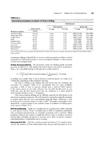
TABLE 23.1 I
General- Recammemlatiuns far Speeds and feeds in Drilling
Drill diameter
Feed, mm/rev Speed, rpm
Surface Speed 1.5 mm 12.5 mm 1.5 mm 12.5 mm
Workpiece material H1/mln
Aluminum alloys 30-120 0.025 0.30 6400-25,000 800-3000
Magnesium alloys 0.025 0.30 9600-25,000 1 100-3000
Copper alloys 0.025 0.25 3200-12,000 400-1500
Steels 0.025 0.30 4300-6400 500-800
Stainless steels 0.025 0.18 2100-4300 250-500
Titanium alloys 0.010 0.15 1300-4300 150-500
Cast irons 0.025 0.30 4300-12,000 500-1500
Thermoplastics 0.025 0.13 6400-12,000 800-1500
Thermosets 0.025 0.10 4300-12,000 500-1500
Note: As hole depth increases, speeds and feeds should be reduced. The selection of speeds and feeds also depends on the specific surface
finish required.
minimizing walking of the drill bit are to use a centering punch to produce an initial
impression in which drilling starts or else to incorporate dimples or other features
into the cast or forged blank.
Drilling Recommendations. Recommended ranges for drilling speeds and feeds
are given in Table 23.11. The speed is the surface speed of the drill at its periphery.
Thus, a 12.7-mm drill rotating at 300 rpm has a surface speed of
v= Qjlmm (300 rev/min)(2¢rrad/rev) @m/mm = 12 m/mm
In drilling holes smaller than 1 mm in diameter, rotational speeds can range up to
30,000 rpm, depending on the workpiece material.
The feed in drilling is the distance the drill travels into the workpiece per
revolution. For example, Table 23.11 recommends that, for most workpiece
materials, a drill 1.5 mm in diameter should have a feed of 0.025 mm/rev.
If the speed column in the table indicates that the drill should rotate at, say,
2000 rpm, then the drill should travel into the workpiece at a linear speed of
(0.025 mm/rev)(2000 rev/min) = 50 mm/min.
C/vip remoz/al during drilling can be difficult, especially for deep holes in soft
and ductile workpiece materials. The drill should be retracted periodically (pecking)
to remove chips that may have accumulated along the flutes. Otherwise, it may
break because of excessive torque, or it may “walk” off location and produce a mis-
shaped hole. A general guide to the probable causes of problems in drilling opera-
tions is given in Table 23.12.
Drill Reconditioning. Drills are reconditioned by grinding them either manually
or with special fixtures. Proper reconditioning of drills is important, particularly
with automated manufacturing on computer numerical control machines. Hand
grinding is difficult and requires considerable skill in order to produce symmetric
cutting edges. Grinding on fixtures is accurate and is done on special computer-
controlled grinders. Coated drills can be recoated.
Measuring Drill Life. Drill life, as well as tap life (see Section 23.7) usually is meas-
ured by the number of holes drilled before they become dull and need to be re-