
Page 669 - Manufacturing Engineering and Technology - Kalpakjian, Serope : Schmid, Steven R.
P. 669
0 Chapter 23 Machining Processes: Turning and Hole Making
TABLE 23.l2
General Troubleshooting Guide for Drilling Operations
Problem Probable causes
Drill breakage Dull drill, drill seizing in hole because of chips clogging flutes,
feed too high, lip relief angle too small
Excessive drill wear Cutting speed too high, ineffective cutting fluid, rake angle too
high, drill burned and strength lost when drill was sharpened
Tapered hole Drill misaligned or bent, lips not equal, web not central
Oversize hole Same as previous entry, machine spindle loose, chisel edge not
central, side force on workpiece
Poor hole surface finish Dull drill, ineffective cutting fluid, welding of workpiece material
on drill margin, improperly ground drill, improper alignment
4' l Radial arm
Fixed head “gf j
(power head) "°fff t,», 13, ,,
"ff V - Hand wheel
Spindle ’“”C°|Um" Q9
Adjustablehead
/
Hand wheel '_ Chuck
Chuck
Base _ Table
Spindle 3
f
Table V _
(3) (D)
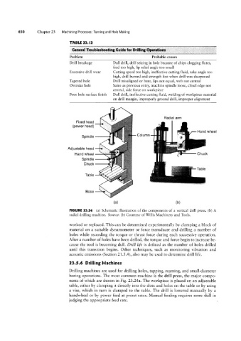
FIGURE 23.24 (a) Schematic illustration of the components of a vertical drill press. (b) A
radial drilling machine. Source: (b) Courtesy of Willis Machinery and Tools.
worked or replaced. This can be determined experimentally by clamping a block of
material on a suitable dynamometer or force transducer and drilling a number of
holes while recording the torque or thrust force during each successive operation.
After a number of holes have been drilled, the torque and force begin to increase be-
cause the tool is becoming dull. Drill life is defined as the number of holes drilled
until this transition begins. Other techniques, such as monitoring vibration and
acoustic emissions (Section 21.5.4), also may be used to determine drill life.
23.5.6 Drilling Machines
Drilling machines are used for drilling holes, tapping, reaming, and small-diameter
boring operations. The most common machine is the drill press, the major compo-
nents of which are shown in Fig. 23.24a. The workpiece is placed on an adjustable
table, either by clamping it directly into the slots and holes on the table or by using
a vise, which in turn is clamped to the table. The drill is lowered manually by a
handwheel or by power feed at preset rates. Manual feeding requires some skill in
judging the appropriate feed rate.