
Page 674 - Manufacturing Engineering and Technology - Kalpakjian, Serope : Schmid, Steven R.
P. 674
Summary
Plate Retainer Bone screw
I I I
f
ffm
Screw and retainer
inserted in plate
(H)
1.3 1 0.075
\ __».f...“.1l..5_. _-e
. 3X 6.68 R = 0.25 i
2X 120° S 10] l 0.28 1.52 R i 0.025
T
\/
60° 3X R = 3_32 | | R = 10.8
4> 9.5
l +0.04O '
2.50 _QOOOO HEX
Note: Thread must start at point S to ensure that retainer interferes with bone screw.
(D)
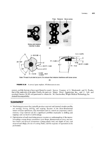
FIGURE 23.28 A cervical spine implant. All dimensions in mm.
corners, and the bottom is heavy-grit blasted to match Source: Courtesy of ]. Mankowski and B. Pyszka
that of the underside of the plate. Finally, the parts are Master Metal Engineering Inc., and C. Lyle and
anodized (Section 3410) and passivated to obtain the M. Handwerker, Wright Medical Technology, Inc
desired biocompatibility.
SUMMARY
Machining processes that typically produce external and internal circular profiles
are turning, boring, drilling, and tapping. Because of the three-dimensional
nature of these operations, chip movement and its control are important consid-
erations. Chip removal can be a significant problem (especially in drilling and
tapping) and can lead to tool breakage.
Optimization of each machining process requires an understanding of the interre-
lationships among design parameters (part shape, dimensional accuracy, and sur-
face finish) and process parameters (cutting speed, feed, and depth of cut), tool
material and shape, the use of cutting fluids, and the sequence of operations to be
performed.