
Page 670 - Manufacturing Engineering and Technology - Kalpakjian, Serope : Schmid, Steven R.
P. 670
Section 23.5 Drilling, Drills, and Drilling Machines 65|
Drill presses usually are designated by the largest workpiece diam-
eter that can be accommodated on the table and typically range from
150 to 1250 mm. In order to maintain proper cutting speeds at the cut-
ting edges of drills, the spindle speed on drilling machines has to be ad- l Column
justable to accommodate different drill sizes. Adjustments are made by
means of pulleys, gearboxes, or variable-speed motors.
The types of drilling machines range from simple hench- l- Turret
type drills used to drill small-diameter holes to large radial drills
(Fig. 23.24b), which can accommodate large workpieces. The distance
between the column and the spindle center can be as much as 3 m. The Table
drill head of universal drilling machines can be swiveled to drill holes
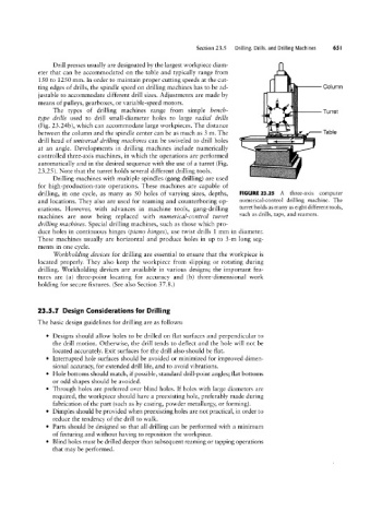
at an angle. Developments in drilling machines include numerically
controlled three-axis machines, in which the operations are performed
automatically and in the desired sequence with the use of a turret (Fig.
23.25). Note that the turret holds several different drilling tools.
Drilling machines with multiple spindles (gang drilling) are used
for high-production-rate operations. These machines are capable of
drilling, in one cycle, as many as 50 holes of varying sizes, depths, FIGURE 23.25 A three-axis computer
and locations. They also are used for reaming and counterboring op- numerical-control drilling machine. The
erations. However, with advances in machine tools, gang-drilling turret holds as many as eight different tools,
machines are now being replaced with numerical-control turret such as drills, taps, and reamers.
drilling machines. Special drilling machines, such as those which pro-
duce holes in continuous hinges (piano hinges), use twist drills 1 mm in diameter.
These machines usually are horizontal and produce holes in up to 3-m long seg-
ments in one cycle.
Worleholding dei/ices for drilling are essential to ensure that the workpiece is
located properly. They also keep the workpiece from slipping or rotating during
drilling. Workholding devices are available in various designs; the important fea-
tures are (a) three-point locating for accuracy and lb) three-dimensional work
holding for secure fixtures. (See also Section 3'/.8.)
23.5.1 Design Considerations for Drilling
The basic design guidelines for drilling are as follows:
° Designs should allow holes to be drilled on flat surfaces and perpendicular to
the drill motion. Otherwise, the drill tends to deflect and the hole will not be
located accurately. Exit surfaces for the drill also should be flat.
° Interrupted hole surfaces should be avoided or minimized for improved dimen-
sional accuracy, for extended drill life, and to avoid vibrations.
° Hole bottoms should match, if possible, standard drill-point angles; flat bottoms
or odd shapes should be avoided.
° Through holes are preferred over blind holes. If holes with large diameters are
required, the workpiece should have a preexisting hole, preferably made during
fabrication of the part (such as by casting, powder metallurgy, or forming).
° Dimples should be provided when preexisting holes are not practical, in order to
reduce the tendency of the drill to walk.
° Parts should be designed so that all drilling can be performed with a minimum
of fixturing and without having to reposition the workpiece.
° Blind holes must be drilled deeper than subsequent reaming or tapping operations
that may be performed.