
Page 679 - Manufacturing Engineering and Technology - Kalpakjian, Serope : Schmid, Steven R.
P. 679
I
0 Chapter 24 Machining Processes: Milling, Broaching, Sawing, Filing, and Gear Manufacturing
Q
¥% i l
(2) (bi eaacece (C)
Stepped Drilled and
cavity tapped holes
1
_
_
5
(G) (ei (fi
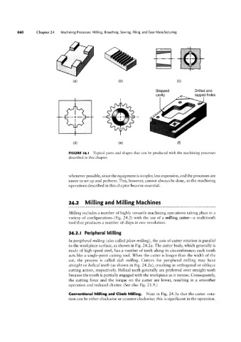
FIGURE 24.l Typical parts and shapes that can be produced with the machining processes
described in this chapter.
whenever possible, since the equipment is simpler, less expensive, and the processes are
easier to set up and perform. This, however, cannot always be done, so the machining
operations described in this chapter become essential.
24.2 Milling and Milling Machines
Milling includes a number of highly versatile machining operations taking place in a
variety of configurations (Fig. 24.2) with the use of a milling cutter-a multitooth
tool that produces a number of chips in one revolution.
24.2.l Peripheral Milling
In peripheral milling (also called plain milling), the axis of cutter rotation is parallel
to the workpiece surface, as shown in Fig. 24.2a. The cutter body, which generally is
made of high-speed steel, has a number of teeth along its circumference; each tooth
acts like a single-point cutting tool. When the cutter is longer than the width of the
cut, the process is called slah milling. Cutters for peripheral milling may have
straight or helical teeth (as shown in Fig. 24.2a), resulting in orthogonal or oblique
cutting action, respectively. Helical teeth generally are preferred over straight teeth
because the tooth is partially engaged with the workpiece as it rotates. Consequently,
the cutting force and the torque on the cutter are lower, resulting in a smoother
operation and reduced chatter. (See also Fig. 21.9.)
Conventional Milling and Climb Milling. Note in Fig. 24.3a that the cutter rota-
tion can be either clockwise or counter-clockwise; this is significant in the operation.