
Page 682 - Manufacturing Engineering and Technology - Kalpakjian, Serope : Schmid, Steven R.
P. 682
Section 24.2 Milling and Milling Machines
tc, can be calculated from the equation
af
= 2 - D,
ff f (24 2)
.
where f is the feed per tooth of the cutter-that is, the distance the workpiece trav-
els per tooth of the cutter, in mm/tooth-and a' is the depth of cut. As tg becomes
larger, the force on the cutter tooth increases.
Feed per tooth is determined from the equation
f= E, (24-3)
U
where 1/ is the linear speed (feed rate) of the workpiece and n is the number of teeth
on the cutter periphery. The dimensional accuracy of this equation can be checked
by using appropriate units for the individual terms; for instance,
(mm/tooth) = (m/min)(103 mm/m)/(rev/min)(number of teeth/rev).
The cutting time, 15, is given by the equation
t = 4,
I+]
1/ (24.4)
where I is the length of the workpiece (Fig. 24.3c) and lc is the horizontal extent of
the cutter’s first contact with the workpiece. Based on the assumption that I, << I
(although this generally is not the case), the material-removal rate (MRR) is
MRR = @ = H/dv, (24.5)
where 1/U is the width of the cut, which in slab milling is the same as the width of the
workpiece. As stated in Section 23.2, the distance that the cutter travels in the non-
cutting cycle of the milling operation is an important economic consideration and
should be minimized by means such as faster travel of the machine tool components.
The foregoing equations and the terminology used are summarized in Table 24.1.
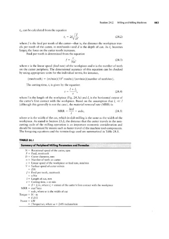
TABLE 24.1
Summary of Peripheral Milling Parameters and Formulas
N = Rotational speed of the cutter, rpm
F = Feed, mm/tooth
D = Cutter diameter, mm
n = Number of teeth on cutter
1/ = Linear speed of the workpiece or feed rate, mm/min
V = Surface speed of cutter m/min
= DN
f= Feed per tooth, mm/tooth
= 1//Nn
I = Length of cut, mm
t = Cutting time, s or min
= (I + IC)/1/, where lc = extent of the cutter’s first contact with the workpiece
MRR = mm3/min
= u/dv, where 1/U is the width of cut
Torque = N - m
- PCD/2
Power = kW
= (Torque)(w), where w = 27TN radians/min