
Page 687 - Manufacturing Engineering and Technology - Kalpakjian, Serope : Schmid, Steven R.
P. 687
668 Chapter 24 Machining Processes: Milling, Broaching, Sawing, Filing, and Gear Manufacturing
End mills are available with hemispherical ends (bull nose mills)
for the production of sculptured surfaces, such as on dies and molds.
Hollow end mills have internal cutting teeth and are used to machine
the cylindrical surfaces of solid, round workpieces. End milling can
produce a variety of surfaces at any depth, such as curved, stepped, and
pocketed (Fig. 24.2d). The cutter can remove material on both its end
and its cylindrical cutting edges, as can be seen in Fig. 24.2c. Both ver-
tical spindle and horizontal spindle machines, as well as machining
centers, can be used for end milling workpieces of various sizes and
shapes. The machines can be programmed such that the cutter can fol-
low a complex set of paths that optimize the whole machining opera-
tion for productivity and minimum cost.
High-speed End Milling. High-speed machining and its applications
are described in Section 25.5. High-speed end milling has become an
important process with numerous applications, such as the milling of
large aluminum-alloy aerospace components and honeycomb struc-
tures with spindle speeds in the range from 20,000 to 60,000 rpm. The
machines must have high stiffness and accuracy, usually requiring
FIGURE 244° 381111056 end mills-These hydrostatic or air bearings, as well as high-quality work-holding
euteefs are able to Pfoduee slabofafs devices. The spindles have a rotational accuracy of 10 /aim; thus, the
contours and are used often in the machin- workpiece surface is also very accurate. At such high rates of material
ing of dies and molds. (See also Fig. 24.2d.) removal, chip collection and disposal can be a significant problem, as
Source: Courtesy of Dijet, Inc. discussed in Section 23.3.7.
The production of cavities in metalworking dies
forming-also is done by high-speed end milling, often
'T Arbor (die sinking)-such as in forging or in sheet-metal
TiAlN-coated ball nose end mills (Fig. 2410).
using
The machines have four-axis or Hr/e~axis movements
ii
We
s
he H” fl (see, for example, Fi g . 24_18) and are able to
W
>< 6 m and weighing
accommodate dies as large as 3
55 metric tons. It is not surprising, then, that such dies
it a very complex shapes in a single setup, (b) can use
machines are that they (a) are capable of machining
(al straddle milling lb) Form milling can cost over $2 million. The advantages of five-axis
W
ma,
shorter cutting tools (thus reducing the tendency for
i lg X f" vibration), and (c) enable drilling of holes at various
f;3;§;;i a
compound angles.
ii
and Milling Cutters
le) S'°“'"9 ‘”'e _ 24.2.4 Other Milling Operations
(dl S"tl"‘9
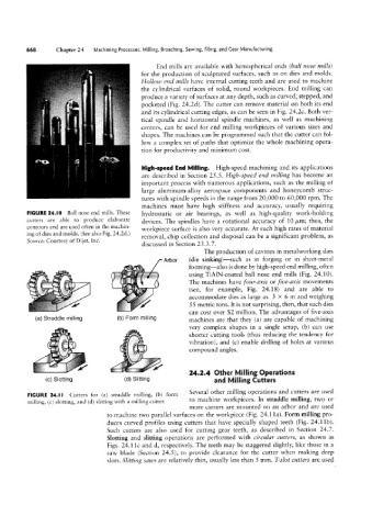
Several other milling operations and cutters are used
Cutters for (a) straddle milling, (b) form
FIGURE 24.I I to machine workpieces. In straddle milling, two or
milling, (c) slotring, and (d) slitting with a milling cutter.
more cutters are mounted on an arbor and are used
to machine two parallel surfaces on the workpiece (Fig. 24.l1a). Form milling pro-
duces curved profiles using cutters that have specially shaped teeth (Fig. 24.11b).
Such cutters are also used for cutting gear teeth, as described in Section 24.7.
Slotting and slitting operations are performed with circular cutters, as shown in
Figs. 24.11c and d, respectively. The teeth may be staggered slightly, like those in a
saw blade (Section 24.5), to provide clearance for the cutter when making deep
slots. Slitting sau/s are relatively thin, usually less than 5 mm. T~slot cutters are used