
Page 688 - Manufacturing Engineering and Technology - Kalpakjian, Serope : Schmid, Steven R.
P. 688
Key seat cutters are used to make the semicylin~
then the cutter machines the complete profile of the Section 24.2 uf Milling and Milling Machines 669
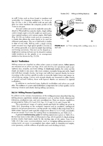
Fig. 24.12a, a slot is first milled with an end mill; 3
to mill T-slots, such as those found in machine-tool
First cut
__
worktables for clamping workpieces. As shown in
,,l; ,Z
(Sl011lnQl
u_5e¢O|-1d out
cutters (single-angle or double-angle) are used to pro- Workplece $7
duce tapered surfaces with various angles. Shell mills
(gy/_
T-slot in one pass.
ll;
1
drical (or Woodruff) key seats for shafts. Angle milling
(Fig. 24.12b) are hollow inside and are mounted on ‘\!\\sv»""
a shank; this allows the same shank to be used for -l-'Slot
different-sized cutters. The use of shell mills is similar la) (bl
to that of end mills. Milling with a single cutting
tooth mounted on a high-speed spindle is known as FIGURE 24.l2 (a) T-slot cutting with a milling cutter. (b) A
fly cutting; generally, it is used in simple face-milling $11611 H1111-
and boring operations. This tool can be shaped as a
single-point cutting tool and can be placed in various
radial positions on the spindle in an arrangement
similar to that shown in Fig. 23.23b.
24.2.5 Toolholders
Milling cutters are classified as either arbor cutters or shank cutters. Arbor cutters
are mounted on an arbor (see Figs. 24.11 and 24.15a), for operations such as pe-
ripheral, face, straddle, and form milling. In shank-type cutters, the cutter and the
shank are made in one piece-the most common examples being end mills. Small
end mills have straight shanks, but larger end mills have tapered shanks for better
mounting in the machine spindle in order to resist the higher forces and torque in-
volved during cutting. Cutters with straight shanks are mounted in collet chucks
or special end-mill holders; those with tapered shanks are mounted in tapered
toolholders.
In addition to mechanical types, hydraulic toolholders and arbors are avail-
able. The stiffness of cutters and toolholders is important for surface quality and in
reducing vibration and chatter during milling operations.
24.2.6 Milling Process Capabilities
ln addition to the various characteristics of the milling processes described thus far,
milling process capabilities include parameters such as surface finish, dimensional
tolerances, production rate, and cost considerations. Data on process capabilities
are presented in Tables 23.1 and 23.8, Figs. 23.13 and 23.14, and Chapter 40.
The conventional ranges of cutting speeds and feeds for milling are given in
Table 24.2. Depending on the workpiece material and its condition, cutting-tool
material, and process parameters, cutting speeds vary widely in the range from 30 to
3000 m/min. Feed per tooth typically ranges from about 0.1 to 0.5 mm, and depths
of cut are usually 1 to 8 mm. For cutting-fluid recommendations, see Table 23.5.
A general troubleshooting guide for milling operations is given in Table 24.3;
the last four items in this table are illustrated in Figs. 24.13 and 24.14. Back striking
involves double feed marks made by the trailing edge of the cutter. Note from
Table 24.3 that some recommendations (such as changing milling parameters or
cutting tools) are easier to accomplish than others (such as changing tool angles,
cutter geometry, and the stiffness of spindles and work-holding devices).