
Page 693 - Manufacturing Engineering and Technology - Kalpakjian, Serope : Schmid, Steven R.
P. 693
674 Chapter 24 Machining Processes: Milling, Broaching, Sawing, Filing, and Gear Manufacturing
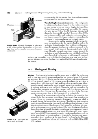
movement (Fig. 24.18); note the three linear and two angular
movements of the machine components.
Column
Work-holding Devices and Accessories. The workpiece to
Workpiece be milled must be clamped securely to the worktable in order
to resist cutting forces and prevent slipping during milling.
Tame Various fixtures and vises generally are used for this purpose.
(See also Section 37.8 on flexible Hxturing.) Mounted and
clamped to the worktable using the T-slots seen in Figs. 24. 15 a
and b, vises are used for small production work on small parts
Base and fixtures are used for higher production work and can be
automated by various mechanical and hydraulic means.
Accessories for milling machines include various fix-
tures and attachments for the machine head (as well as the
FIGURE 24.I8 Schematic illustration of a five-axis worktable) designed to adapt them to different milling opera-
profile milling machine. Note that there are three prin- tions. The accessory that has been used most commonly in the
cipal linear and two angular movements of machine past, typically in job shops, is the universal dividing (index)
C0mP0U€UfS- head. Manually operated, this fixture rotates (indexes) the
workpiece to specified angles between individual machining
steps. Typically, it has been used to mill parts with polygonal
surfaces and to machine gear teeth. Dividing heads are now used only for low-
volume job-shop quantities; they have been replaced by CNC controls and machin-
ing centers.
24.3 Planing and Shaping
Planing. This is a relatively simple machining operation by which flat surfaces, as
well as cross sections with grooves and notches, are produced along the length of
the workpiece (Fig. 24.19). Planing usually is done on large workpieces, as large as
25 >< 15 m, although a length of 10 m is more typical. In a planet, the workpiece is
mounted on a table that travels back and forth along a straight path. A hori-
zontal cross-rail, which can be moved vertically along the ways of the column,
is equipped with one or more tool heads. The cutting tools are mounted on the
heads, and the machining is done along a straight path. In order to prevent tool
cutting edges from chipping when they rub along a workpiece during the return
stroke, tools are either tilted or lifted mechanically or hydraulically.
Because of the reciprocating motion of the workpiece, the noncutting time
elapsed during the return stroke is significant. Consequently, these operations are
neither efficient nor economical (except for low-quantity production, which is
generally the case for large and long workpieces). The efficiency of the operation
can be improved by equipping planers with toolholders and tools that cut in both
directions of table travel. Also, because of the length of the workpiece, it is essen-
tial to equip cutting tools with chip breakers. Otherwise, the chips produced can
be very long, interfering with the planing operation and becoming a safety hazard.
Cutting speeds in planers can range up to 120 m/min, with power capaci-
ties of up to 1 10 kW Recommended speeds for cast irons and stainless steels are
in the range from 3 to 6 m/min and up to 90 m/min for aluminum and magne-
sium alloys. Feeds usually are in the range from 0.5 to 3 mm/stroke. The most
FIGURE 24.l9 Typical parts that common tool materials are M2 and M3 high-speed steels and K20 (C2) and P20
can be made on a planer. (C6) carbides.