
Page 698 - Manufacturing Engineering and Technology - Kalpakjian, Serope : Schmid, Steven R.
P. 698
Section 24 5 Sawing
Ripping Internal cuts Angular cuts
(H) (b) (C)
lngot
Wafer being
1
sliced
Diamond
cutting edge
Saw blade
Contour cutting Stack cutting “' Feed
(Cl) (9) (fl
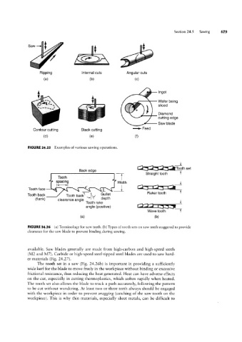
FIGURE 24.25 Examples of various sawing operations.
4
Tooth set
B k d
ac e ge Straight tooth
Tooth T
s ac’n Q Width i
P
l
Tooth face i __T
Tggth back Tooth backi \'\/ Gullet Ftaker tooth
(flank) clearance angle depth
Tooth rake “’*3§__
angle (positive)
Wave tooth T
(3) (D)
FIGURE 24.26 (a) Terminology for saw teeth. (b) Types of tooth sets on saw teeth staggered to provide
clearance for the saw blade to prevent binding during sawing.
available. Saw blades generally are made from high-carbon and high-speed steels
(MZ and M7). Carbide or high-speed steel-tipped steel blades are used to saw hard-
er materials (Fig. 2427).
The tooth set in a saw (Fig. 24.26b) is important in providing a sufficiently
wide kerf for the blade to move freely in the workpiece without binding or excessive
frictional resistance, thus reducing the heat generated. Heat can have adverse effects
on the cut, especially in cutting thermoplastics, which soften rapidly when heated.
The tooth set also allows the blade to track a path accurately, following the pattern
to be cut without wandering. At least two or three teeth always should be engaged
with the workpiece in order to prevent snagging (catching of the saw tooth on the
workpiece). This is why thin materials, especially sheet metals, can be difficult to