
Page 690 - Manufacturing Engineering and Technology - Kalpakjian, Serope : Schmid, Steven R.
P. 690
Section 24.2 Milling and Milling Machines
Cutter Milled Chatter
Milled surface (YOD view) Surface
fv*i'v'v'r'v'v'y'yxe'@'l
ii.iii.l.ltitiliil <1 *-
<T'*
Back striking No back striking
Direction of workpiece travel
(fi) (bl
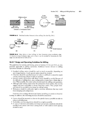
FIGURE 24.I3 Machined surface features in face milling. (See also Fig. 24.6.)
Cutter
Insert lgzgiout
Uk Burr l%‘
‘_ Small breakout
(G) (bl (C)
FIGURE 24.l4 Edge defects in face milling: (a) burr formation along workpiece edge,
(bl breakout along workpiece edge, and (c) how it can be avoided by increasing the lead
angle (see also last row in Table 243).
24.2.7 Design and Operating Guidelines for Milling
The guidelines for turning and boring, given in Sections 23.3.6 and 23.4, are also
generally applicable to milling operations. Additional factors relevant to milling
operations include the following:
° Standard milling cutters should be used as much as possible, depending on
part design features. Costly special cutters should be avoided.
° Chamfers should be specified instead of radii; it is difficult to smoothly match
various intersecting surfaces if radii are specified.
' Internal cavities and pockets with sharp corners should be avoided because of
the difficulty of milling them, since cutting teeth or inserts have a finite edge ra-
dius. When possible, the corner radius should match the milling cutter geometry.
° Although small milling cutters allow the production of any surface, they are less
rugged and more susceptible to chatter than large cutters. Thus, proper clear-
ance should be provided in the design for milling cutters.
° Workpieces should be sufficiently rigid to minimize deflections that may result
from clamping and cutting forces.
Guidelines for avoiding vibration and chatter in milling are similar to those for
turning. In addition, the following practices should be considered:
° Cutters should be mounted as close to the spindle base as possible in order to
reduce tool deflections.
° Toolholders and fixturing devices should be as rigid as possible.
° In cases of vibration and chatter, tool shape and process conditions should be
modified and cutters with fewer cutting teeth or with random tooth spacing
should be used.