
Page 685 - Manufacturing Engineering and Technology - Kalpakjian, Serope : Schmid, Steven R.
P. 685
666 Chapter 24 Machining Processes: Milling, Broaching, Sawing, Filing, and Gear Manufacturing
End cutting-edge angle-\ Peripheral' relief
u r
(radial relief)
_
/. N
' Corner
angle
End relief _ _
Axial rake, +
rake, -
(axial relief) Radial ea
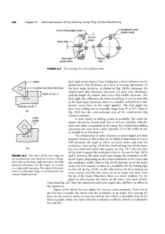
FIGURE 24.7 Terminology for a face-milling cutter.
_ Insert lead angle of the insert in face milling has a direct influence on the
andefowned chip thickness, as it does in turning operations. As
V- Undeformed chip thickness the lead angle (positive, as shown in Fig. 24.8b) increases, the
undeformed chip thickness decreases (as does chip thickness),
Depth of cut, d
and the length of contact (and hence chip width) increases. The
lead angle also influences the forces in milling. It can be seen that
as the lead angle decreases, there is a smaller vertical-force com-
ponent (axial force on the cutter spindle). The lead angles for
Feed per tooth, f
most face~milling cutters typically range from 0° to 45°. Note in
(al Fig. 24.8 that the cross-sectional area of the undeformed chip
remains constant.
Lead A wide variety of milling cutters is available. The cutter di-
ameter should be chosen such that it will not interfere with fix-
tures and other components in the setup. In a typical face-milling
operation, the ratio of the cutter diameter, D, to the width of cut,
w, should be no less than 3:2.
The relationship of cutter diameter to insert angles and their
position relative to the surface to be milled is important in that it
will determine the angle at which an insert enters and exits the
workpiece. Note in Fig. 24.4b for climb milling that (if the insert
(bl has zero axial and radial rake angles, see Fig. 24.7) the rake face
of the insert engages the workpiece directly. As seen in Figs. 24.9a
FIGURE 24.8 The effect of the lead angle on and b, however, the same insert may engage the workpiece at dif-
the undeformed chip thickness in face milling. ferent angles, depending on the relative positions of the cutter and
Note that as the lead angle increases, the chip the workpiece width. Note in Fig. 24.9a that the tip of the insert
thickness decreases, but the length of contact makes the first contact, so there is a possibility for the cutting edge
(i.e., chip width) increases. The edges of the insert to chip off. In Fig. 24.9b, on the other hand, the first contacts (at
must be sufficiently large to accommodate the
entry, reentry, and the two exits) are at an angle and away from
contact length increase.
the tip of the insert. Therefore, there is a lower tendency for the
insert to fail, because the forces on the insert vary more slowly.
Note from Fig. 24.7 that the radial and axial rake angles also will have an effect on
this operation.
Figure 24.9c shows the exit angles for various cutter positions. Note that in
the first two examples the insert exits the workpiece at an angle, thus causing the
force on the insert to reduce to zero at a slower rate (which is desirable) than in the
third example, where the insert exits the workpiece suddenly (which is undesirable
for tool life).