
Page 686 - Manufacturing Engineering and Technology - Kalpakjian, Serope : Schmid, Steven R.
P. 686
Section 24.2
Milling and Milling Machines
Entry ;,,,. Exit , 667
Workpiece
Reentry
Exit
+
__ t `»»_;
Cutter
~
Surface
Cutter if iiiii Milled Desirable Undesirable
(3) (bl (C)
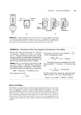
FIGURE 24.9 (a) Relative position of the cutter and insert as they first engage the workpiece
in face milling. (b) Insert positions towards the end of cut. (c) Examples of exit angles of the
insert, showing desirable (positive or negative angle) and undesirable (zero angle) positions.
In all figures, the cutter spindle is perpendicular to the page and rotates clockwise.
EXAMPLE 24.2 Material-removl Rate, Power Required, and Cutting Time in Face Milling
Refer to Fig. 24.4 and assume that D = 150 mm,
Note from Fig. 24.4 that, for this problem, lg = g =
w = 60 mm, I = 500 mm, d = 3 mrn,v = 0.6 m/min,
75 mm. The cutting time is then
and N = 100 rpm. The cutter has 10 inserts, and the
workpiece material is a high-strength aluminum alloy. t= =65s=1.08min.
Calculate the material-removal rate, cutting time, and
feed per tooth, and estimate the power required.
The feed per tooth can be obtained from Eq. (24.3).
Solution First we note that the cross section of the Observing that N == 100 rpm = 1.67 rev/s, we find
cut is wd = (60)(3) = 180 mmz. Then, noting that
that
the workpiece speed, 1/, is 0.6 m/min = 600 mm/min,
the material-removal rate (MRR) can be calculated as 10
f- - 0.6 mm/t0Oth.
MRR = (180)(600) = 108,000 mm3/min.
The cutting time is given by For this material, let’s estimate the unit power from
Table 21.2 to be 1.1 W ' s/mm3. Thus, the power is
v Power = (1.1)(1800) = 1980 W = 1.98 kv/_
24.2.3 End Milling
End milling is an important and common machining operation because of its versa-
tility and capability to produce various profiles and curved surfaces. The cutter,
called an end mill (Fig. 24.2c) has either a straight shank (for small cutter sizes) or a
tapered shank (for larger sizes) and is mounted into the spindle of the milling ma-
chine. End mills may be made of high-speed steels or with carbide inserts, similar to
those for face milling. The cutter usually rotates on an axis perpendicular to the
workpiece surface, and it also can be tilted to conform to machine-tapered or curved
surfaces.