
Page 681 - Manufacturing Engineering and Technology - Kalpakjian, Serope : Schmid, Steven R.
P. 681
2 Chapter 24 Machining Processes: Milling, Broaching, Sawing, Filing, and Gear Manufacturing
In conventional milling (also called up milling), the maximum chip thickness is at
the end of the cut as the tooth leaves the workpiece surface. The advantages to con-
ventional milling are that (a) tooth engagement is not a function of workpiece sur-
face characteristics and (b) contamination or scale (oxide layer) on the surface does
not adversely affect tool life. This is the more common method of milling. The cut-
ting process is smooth, provided that the cutter teeth are sharp. Otherwise, the tooth
will rub against and smear the surface for some distance before it begins to cut. Also,
there may be a tendency for the tool to chatter, and the workpiece has a tendency to
be pulled upward (because of the cutter rotation direction), necessitating proper
clamping.
In climb milling (also called down milling), cutting starts at the surface of the
workpiece where the chip is thickest. The advantage is that the downward compo-
nent of the cutting force holds the workpiece in place, particularly for slender parts.
However, because of the resulting impact forces when the teeth engage the work-
piece, this operation must have a rigid work-holding setup, and gear backlash must
be eliminated in the table feed mechanism. Climb milling is not suitable for the ma-
chining of workpieces having surface scale, such as hot-worked metals, forgings,
and castings. The scale is hard and abrasive and causes excessive wear and damage
to the cutter teeth, thus shortening tool life.
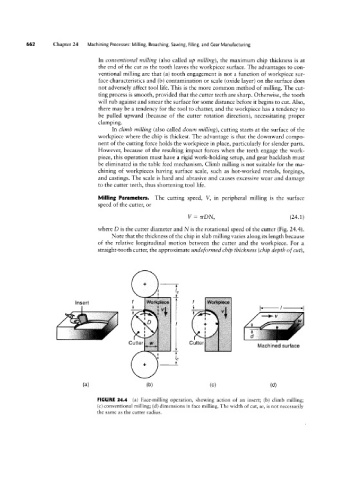
Milling Parameters. The cutting speed, V, in peripheral milling is the surface
speed of the cutter, or
V = ¢rDN, (24.1)
where D is the cutter diameter and N is the rotational speed of the cutter (Fig. 24.4).
Note that the thickness of the chip in slab milling varies along its length because
Insert
of the relative longitudinal motion between the cutter and the workpiece. For a
straight-tooth cutter, the approximate undeformed chip thickness (chip depth of cut),
TL
T;
“ll”
Cutter 'C Cutter l‘T’i’l
:
1- f‘e"
f
f
ese
| /C (.e. il; ip Machined surface
__l_
(H) (b) (C) (dl
FIGURE 24.4 (a) Face-milling operation, showing action of an insert; (b) climb milling;
(c) conventional milling; (d) dimensions in face milling. The width of cut, uf, is not necessarily
the same as the cutter radius.