
Page 680 - Manufacturing Engineering and Technology - Kalpakjian, Serope : Schmid, Steven R.
P. 680
,
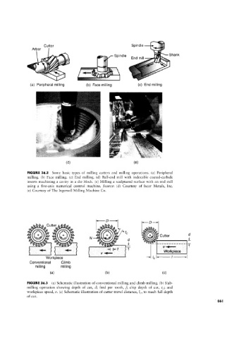
Arbor
Cutter
Spme Spindle Shank
End min
(a) Peripheral milling (b) e milling (c) End milling
(Ol) (9)
FIGURE 24.2 Some basic types of milling cutters and milling operations. la) Peripheral
milling. (b) Face milling. (c) End milling. (d) Ball-end mill with indexable coated-carbide
inserts machining a cavity in a die block. (e) Milling a sculptured surface with an end mill
using a five-axis numerical control machine. Source: (cl) Courtesy of Iscar Metals, Inc.
(e) Courtesy of The Ingersoll Milling Machine Co.
I ,_r;;~¢,
tsts
D
3 5/
A4Cutter ,
tsss
ii
_ig gi Toe] t I;
itawx/i,
‘Q
Y' ff ii; iyyiyy»s i & N 15 Cutter
d
/ii/wi e lm /w e' L i" ~-~-~-~-~----
+i iff T " ‘
V E Workpiece
/c l"“;' '“"’l
Workpieoe /
Conventional Climb
milling milling
(H) (bl (C)
FIGURE 24.3 (a) Schematic illustration of conventional milling and climb milling. (b) Slab-
milling operation showing depth of cut, d; feed per tooth, f; chip depth of cut, tc; and
workpiece speed, 1/_ (c) Schematic illustration of cutter travel distance, IC, to reach full depth
of cut.