
Page 351 - Materials Science and Engineering An Introduction
P. 351
9.12 Development of Microstructure in Eutectic Alloys • 323
Tutorial Video: L
Eutectic Reaction (C 4 wt% Sn) z
Vocabulary and j 600
Microstructures 300 L
Which Eutectic
Microstructures go with + L L 500
Which Regions on a
Eutectic Phase Diagram? (18.3
wt% Sn) k 400
Temperature (°C) L (61.9 wt% Sn) m l Eutectic + L Temperature (°F)
200
structure
Primary 300
+ (18.3 wt% Sn)
100
200
(97.8 wt% Sn)
Eutectic
(18.3 wt% Sn)
100
z
0
0 20 60 80 100
(Pb) C 4 (Sn)
(40)
Photomicrograph
showing a reversible- Composition (wt% Sn)
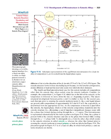
matrix interface (i.e., Figure 9.16 Schematic representations of the equilibrium microstructures for a lead–tin
a black-on-white alloy of composition C 4 as it is cooled from the liquid-phase region.
to white-on-black
pattern reversal a
la Escher) for an
aluminum-copper
eutectic alloy. diffusion of tin is in the direction of the b, tin-rich (97.8 wt% Sn–2.2 wt% Pb) layers. The
Magnification un- eutectic structure forms in these alternating layers because, for this lamellar configuration,
known. atomic diffusion of lead and tin need only occur over relatively short distances.
(From Metals The fourth and final microstructural case for this system includes all compositions
Handbook, Vol. 9, 9th other than the eutectic that, when cooled, cross the eutectic isotherm. Consider, for
edition, Metallography example, the composition C 4 in Figure 9.16, which lies to the left of the eutectic; as the
and Microstructures, temperature is lowered, we move down the line zz¿, beginning at point j. The micro-
1985. Reproduced by is similar to that for the second case,
permission of ASM structural development between points j and l
International, Materials such that just prior to crossing the eutectic isotherm (point l), the a and liquid phases
Park, OH.) are present with compositions of approximately 18.3 and 61.9 wt% Sn, respectively, as
determined from the appropriate tie line. As the temperature is lowered to just below
the eutectic, the liquid phase, which is of the eutectic composition, transforms into the
eutectic structure (i.e., alternating a and b lamellae); insignificant changes occur with
the a phase that formed during cooling through the a + L region. This microstructure
is represented schematically by the inset at point m in Figure 9.16. Thus, the a phase is
: VMSE present both in the eutectic structure and also as the phase that formed while cooling
Eutectic (Pb-Sn)
through the a + L phase field. To distinguish one a from the other, that which resides
eutectic phase in the eutectic structure is called eutectic a, whereas the other that formed prior to
crossing the eutectic isotherm is termed primary a; both are labeled in Figure 9.16. The
primary phase
photomicrograph in Figure 9.17 is of a lead–tin alloy in which both primary a and eu-
tectic structures are shown.