
Page 347 - Materials Science and Engineering An Introduction
P. 347
9.12 Development of Microstructure in Eutectic Alloys • 319
M A T E R I A L S O F I M P O R T A N C E
Lead-Free Solders
olders are metal alloys that are used to bond Table 9.1 Compositions, Solidus Temperatures,
Sor join two or more components (usually other and Liquidus Temperatures for Two
metal alloys). They are used extensively in the Lead-Containing Solders and Five
electronics industry to physically hold assemblies Lead-Free Solders
together; they must allow expansion and contraction
Liquidus
Solidus
of the various components, transmit electrical signals, Composition Temperature Temperature
and dissipate any heat that is generated. The bonding
action is accomplished by melting the solder material (wt%) ( C) ( C)
and allowing it to flow among and make contact with Solders Containing Lead
the components to be joined (which do not melt); 63 Sn–37 Pb a 183 183
finally, upon solidification, it forms a physical bond 50 Sn–50 Pb 183 214
with all of these components. Lead-Free Solders
In the past, the vast majority of solders have been 99.3 Sn–0.7 Cu a 227 227
lead–tin alloys. These materials are reliable and inex-
pensive and have relatively low melting temperatures. 96.5 Sn–3.5 Ag a 221 221
The most common lead–tin solder has a composition 95.5 Sn–3.8 217 220
of 63 wt% Sn–37 wt% Pb. According to the lead–tin Ag–0.7 Cu
phase diagram, Figure 9.8, this composition is near the 91.8 Sn–3.4 211 213
eutectic and has a melting temperature of about 183 C, Ag–4.8 Bi
the lowest temperature possible with the existence of 97.0 Sn–2.0
a liquid phase (at equilibrium) for the lead–tin system. Cu–0.85 219 235
This alloy is often called a eutectic lead–tin solder. Sb–0.2 Ag
Unfortunately, lead is a mildly toxic metal, and a
there is serious concern about the environmental impact The compositions of these alloys are eutectic composi-
of discarded lead-containing products that can leach into tions; therefore, their solidus and liquidus temperatures
groundwater from landfills or pollute the air if inciner- are identical.
ated. Consequently, in some countries legislation has
been enacted that bans the use of lead-containing sol- 400
ders. This has forced the development of lead-free sol-
ders that, among other things, must have relatively low L
melting temperatures (or temperature ranges). Many of 300 + L
these are tin alloys that contain relatively low concentra- 221°C 232°C
tions of copper, silver, bismuth, and/or antimony. Com- Temperature (°C) 200 96.5 Sn + L
positions as well as liquidus and solidus temperatures for
several lead-free solders are listed in Table 9.1. Two lead- Sn
containing solders are also included in this table. 100 + Sn
Melting temperatures (or temperature ranges) 13°C
are important in the development and selection of Sn
these new solder alloys, information available from 0 80 90 100
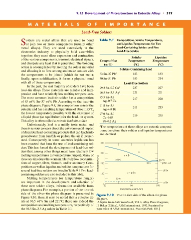
phase diagrams. For example, a portion of the tin-rich Composition (wt% Sn)
side of the silver–tin phase diagram is presented in Figure 9.10 The tin-rich side of the silver–tin phase
Figure 9.10. Here, it may be noted that a eutectic ex- diagram.
ists at 96.5 wt% Sn and 221 C; these are indeed the [Adapted from ASM Handbook, Vol. 3, Alloy Phase Diagrams,
composition and melting temperature, respectively, of H. Baker (Editor), ASM International, 1992. Reprinted by
the 96.5 Sn–3.5 Ag solder in Table 9.1. permission of ASM International, Materials Park, OH.]