
Page 361 - Materials Science and Engineering An Introduction
P. 361
9.18 The Iron–Iron Carbide (Fe–Fe C) Phase Diagram • 333
3
The Iron–Carbon System
Of all binary alloy systems, the one that is possibly the most important is that for iron
and carbon. Both steels and cast irons, primary structural materials in every techno-
logically advanced culture, are essentially iron–carbon alloys. This section is devoted
to a study of the phase diagram for this system and the development of several of the
possible microstructures. The relationships among heat treatment, microstructure, and
mechanical properties are explored in Chapters 10 and 11.
9.18 THE IRON–IRON CARBIDE (Fe–Fe C)
3
PHASE DIAGRAM
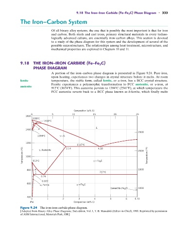
A portion of the iron–carbon phase diagram is presented in Figure 9.24. Pure iron,
upon heating, experiences two changes in crystal structure before it melts. At room
ferrite temperature, the stable form, called ferrite, or a-iron, has a BCC crystal structure.
Ferrite experiences a polymorphic transformation to FCC austenite, or g-iron, at
austenite
912 C (1674 F). This austenite persists to 1394 C (2541 F), at which temperature the
FCC austenite reverts back to a BCC phase known as d-ferrite, which finally melts
Composition (at% C)
0 5 10 15 20 25
1600
1538°C
1493°C
L
1400
2500
1394°C + L
1200
1147°C 4.30
Temperature (°C) 1000 912°C + Fe 3 C 2000 Temperature (°F)
2.14
, Austenite
1500
800
+ 727°C
0.76
0.022
600
, Ferrite + Fe C
3
Cementite (Fe 3 C) 1000
400
0 1 2 3 4 5 6 6.70
(Fe) Composition (wt% C)
Figure 9.24 The iron–iron carbide phase diagram.
[Adapted from Binary Alloy Phase Diagrams, 2nd edition, Vol. 1, T. B. Massalski (Editor-in-Chief), 1990. Reprinted by permission
of ASM International, Materials Park, OH.]