
Page 365 - Materials Science and Engineering An Introduction
P. 365
9.19 Development of Microstructure in Iron–Carbon Alloys • 337
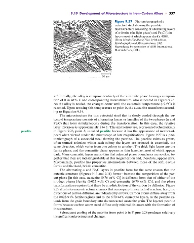
Figure 9.27 Photomicrograph of a
eutectoid steel showing the pearlite
microstructure consisting of alternating layers
of a-ferrite (the light phase) and Fe 3 C (thin
layers most of which appear dark). 470 .
(From Metals Handbook, Vol. 9, 9th edition,
Metallography and Microstructures, 1985.
Reproduced by permission of ASM International,
Materials Park, OH.)
20 m
xx¿. Initially, the alloy is composed entirely of the austenite phase having a composi-
tion of 0.76 wt% C and corresponding microstructure, also indicated in Figure 9.26.
As the alloy is cooled, no changes occur until the eutectoid temperature (727 C) is
reached. Upon crossing this temperature to point b, the austenite transforms accord-
ing to Equation 9.19.
The microstructure for this eutectoid steel that is slowly cooled through the eu-
tectoid temperature consists of alternating layers or lamellae of the two phases (a and
Fe 3 C) that form simultaneously during the transformation. In this case, the relative
layer thickness is approximately 8 to 1. This microstructure, represented schematically
pearlite in Figure 9.26, point b, is called pearlite because it has the appearance of mother-of-
pearl when viewed under the microscope at low magnifications. Figure 9.27 is a pho-
tomicrograph of a eutectoid steel showing the pearlite. The pearlite exists as grains,
often termed colonies; within each colony the layers are oriented in essentially the
same direction, which varies from one colony to another. The thick light layers are the
ferrite phase, and the cementite phase appears as thin lamellae, most of which appear
dark. Many cementite layers are so thin that adjacent phase boundaries are so close to-
gether that they are indistinguishable at this magnification and, therefore, appear dark.
Mechanically, pearlite has properties intermediate between those of the soft, ductile
ferrite and the hard, brittle cementite.
The alternating a and Fe 3 C layers in pearlite form for the same reason that the
eutectic structure (Figures 9.13 and 9.14) forms—because the composition of the par-
ent phase [in this case, austenite (0.76 wt% C)] is different from that of either of the
product phases [ferrite (0.022 wt% C) and cementite (6.70 wt% C)], and the phase
transformation requires that there be a redistribution of the carbon by diffusion. Figure
9.28 illustrates microstructural changes that accompany this eutectoid reaction; here, the
directions of carbon diffusion are indicated by arrows. Carbon atoms diffuse away from
the 0.022-wt% ferrite regions and to the 6.70-wt% cementite layers, as the pearlite ex-
tends from the grain boundary into the unreacted austenite grain. The layered pearlite
forms because carbon atoms need diffuse only minimal distances with the formation of
this structure.
Subsequent cooling of the pearlite from point b in Figure 9.26 produces relatively
insignificant microstructural changes.