
Page 402 - Materials Science and Engineering An Introduction
P. 402
374 • Chapter 10 / Phase Transformations
Figure 10.16 Isothermal transformation 900
diagram for a 1.13 wt% C iron–carbon alloy: 1600
A, austenite; C, proeutectoid cementite;
P, pearlite. A
800
[Adapted from H. Boyer (Editor), Atlas of Isother-
A Eutectoid temperature
mal Transformation and Cooling Transformation + 1400
Diagrams, 1977. Reproduced by permission of ASM
Temperature (°C) A 1200 Temperature (°F)
International, Materials Park, OH.] 700 A C
600 P + P
1000
500
1 10 10 2 10 3 10 4
Time (s)
curves corresponding to a proeutectoid transformation also must be included on the
isothermal transformation diagram. A portion of one such diagram for a 1.13 wt% C
alloy is shown in Figure 10.16.
Bainite
In addition to pearlite, other microconstituents that are products of the austenitic trans-
bainite formation exist; one of these is called bainite. The microstructure of bainite consists of
ferrite and cementite phases, and thus diffusional processes are involved in its formation.
Bainite forms as needles or plates, depending on the temperature of the transformation;
the microstructural details of bainite are so fine that their resolution is possible only using
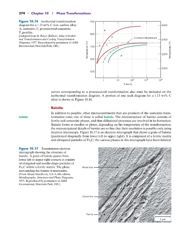
electron microscopy. Figure 10.17 is an electron micrograph that shows a grain of bainite
(positioned diagonally from lower left to upper right). It is composed of a ferrite matrix
and elongated particles of Fe 3 C; the various phases in this micrograph have been labeled.
Figure 10.17 Transmission electron
micrograph showing the structure of
bainite. A grain of bainite passes from
lower left to upper right corners; it consists
of elongated and needle-shape particles of
Fe 3 C within a ferrite matrix. The phase Martensite
surrounding the bainite is martensite.
(From Metals Handbook, Vol. 8, 8th edition,
Metallography, Structures and Phase Diagrams,
1973. Reproduced by permission of ASM
International, Materials Park, OH.)
Cementite
Ferrite