Page 232 - Mechanical design of microresonators _ modeling and applications
P. 232

0-07-145538-8_CH05_231_08/30/05


                                                 Resonant Micromechanical Systems

                                                             Resonant Micromechanical Systems  231


                                   1.04                                      0.1
                              rω I- II
                                b
                                       1
                                       1 1
                                                                           c w


                                                  c l              0.01
                                                                5 5
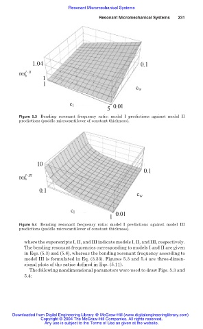
                              Figure 5.3 Bending resonant frequency ratio:  model  I  predictions against model II
                              predictions (paddle microcantilever of constant thickness).


                                     10
                                                                              0.1
                                I- III
                              rω b

                                      0.
                                       1
                                      0.1
                                                                            c w
                                                  c l              0.01
                                                                 1 1
                              Figure 5.4 Bending resonant frequency ratio: model I predictions against model III
                              predictions (paddle microcantilever of constant thickness).

                                where the superscripts I, II, and III indicate models I, II, and III, respectively.
                                The bending resonant frequencies corresponding to models I and II are given
                                in Eqs. (5.3) and (5.8), whereas the bending resonant frequency according to
                                model III is formulated in Eq. (3.33). Figures 5.3 and 5.4 are three-dimen-
                                sional plots of the ratios defined in Eqs. (5.11).
                                  The following nondimensional parameters were used to draw Figs. 5.3 and
                                5.4:


                           Downloaded from Digital Engineering Library @ McGraw-Hill (www.digitalengineeringlibrary.com)
                                      Copyright © 2004 The McGraw-Hill Companies. All rights reserved.
                                        Any use is subject to the Terms of Use as given at the website.
   227   228   229   230   231   232   233   234   235   236   237