
Page 235 - Mechanical design of microresonators _ modeling and applications
P. 235
0-07-145538-8_CH05_234_08/30/05
Resonant Micromechanical Systems
234 Chapter Five
I
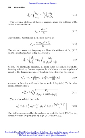
k b,e t 2 Et 2
Ȧ I = = (5.16)
b,e I 2l ȡl l t
m 2 1 2 1
b,e
The torsional stiffness of the root segment gives the stiffness of the
entire microcantilever:
3
Gwt 2
I
k t,e = (5.17)
3l
2
The torsional mechanical moment of inertia is
2
2
ȡl wt (w + t )
I 1 1 1 (5.18)
J t,e = 12
The torsional resonant frequency combines the stiffness of Eq. (5.17)
and the inertia fraction of Eq. (5.18) and is
I
k t,e Gt 2
Ȧ I = =2t (5.19)
t,e I 2 2 2
m t,e ȡl l t (w + t )
1
1 2 1
Model II. As previously specified, model II takes into consideration the
inertia produced by the root segment, in addition to the assumptions of
model I. The lumped-parameter bending-related inertia fraction is
2 2)
m II = m + 33 m = ȡw l t + 33 l t (5.20)
b,e 1 140 2 ( 1 1 140
whereas the bending stiffness is that of model I, Eq. (5.14). The bending
resonant frequency is
t 2 Et 2
II
Ȧ b,e =0.5 (5.21)
l
/
2 ȡl (l t + (33 140)l t )
2 1 1
2 2
The torsion-related inertia is
2
2
2 2
2
2
2
II
J t,e = J + 1 J = ȡw l t (w + t ) + l t (w + t ) (5.22)
1
t2
t1
1 1
3
12
3
The stiffness remains that formulated by model I, Eq. (5.17). The tor-
sional resonant frequency is, by Eqs. (5.17) and (5.22),
Downloaded from Digital Engineering Library @ McGraw-Hill (www.digitalengineeringlibrary.com)
Copyright © 2004 The McGraw-Hill Companies. All rights reserved.
Any use is subject to the Terms of Use as given at the website.