
Page 239 - Mechanical design of microresonators _ modeling and applications
P. 239
0-07-145538-8_CH05_238_08/30/05
Resonant Micromechanical Systems
238 Chapter Five
y
symmetry l 1 + l 2 /2
anchor anchor
line
mass
hinge hinge
x
l 1 l 2 l 1
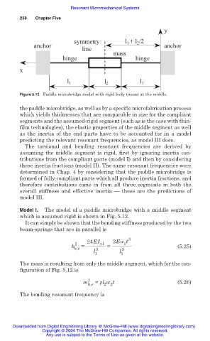
Figure 5.12 Paddle microbridge model with rigid body (mass) at the middle.
the paddle microbridge, as well as by a specific microfabrication process
which yields thicknesses that are comparable in size for the compliant
segments and the assumed-rigid segment (such as is the case with thin-
film technologies), the elastic properties of the middle segment as well
as the inertia of the end parts have to be accounted for in a model
predicting the relevant resonant frequencies, as model III does.
The torsional and bending resonant frequencies are derived by
assuming the middle segment is rigid, first by ignoring inertia con-
tributions from the compliant parts (model I) and then by considering
these inertia fractions (model II). The same resonant frequencies were
determined in Chap. 4 by considering that the paddle microbridge is
formed of fully compliant parts which all produce inertia fractions, and
therefore contributions come in from all three segments in both the
overall stiffness and effective inertia — these are the predictions of
model III.
Model I. The model of a paddle microbridge with a middle segment
which is assumed rigid is shown in Fig. 5.12.
It can simply be shown that the bending stiffness produced by the two
beam-springs that are in parallel is
3
24EI 2Ew t
I y1 1
k = = (5.25)
b,e 3 3
l 1 l 1
The mass is resulting from only the middle segment, which for the con-
figuration of Fig. 5.12 is
m I b,e = ȡl w t (5.26)
2 2
The bending resonant frequency is
Downloaded from Digital Engineering Library @ McGraw-Hill (www.digitalengineeringlibrary.com)
Copyright © 2004 The McGraw-Hill Companies. All rights reserved.
Any use is subject to the Terms of Use as given at the website.