
Page 238 - Mechanical design of microresonators _ modeling and applications
P. 238
0-07-145538-8_CH05_237_08/30/05
Resonant Micromechanical Systems
Resonant Micromechanical Systems 237
1.4
I- II 0.8
rω t
0.6
1
0.
0.1
c t
c l
0.1
1 1
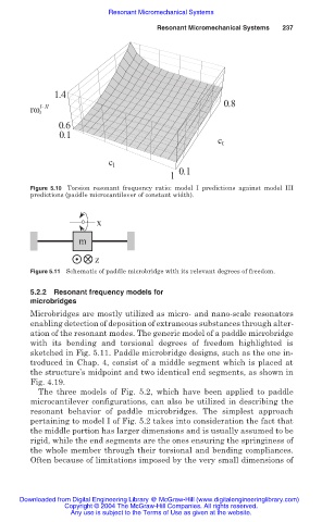
Figure 5.10 Torsion resonant frequency ratio: model I predictions against model III
predictions (paddle microcantilever of constant width).
x
m
z
Figure 5.11 Schematic of paddle microbridge with its relevant degrees of freedom.
5.2.2 Resonant frequency models for
microbridges
Microbridges are mostly utilized as micro- and nano-scale resonators
enabling detection of deposition of extraneous substances through alter-
ation of the resonant modes. The generic model of a paddle microbridge
with its bending and torsional degrees of freedom highlighted is
sketched in Fig. 5.11. Paddle microbridge designs, such as the one in-
troduced in Chap. 4, consist of a middle segment which is placed at
the structure’s midpoint and two identical end segments, as shown in
Fig. 4.19.
The three models of Fig. 5.2, which have been applied to paddle
microcantilever configurations, can also be utilized in describing the
resonant behavior of paddle microbridges. The simplest approach
pertaining to model I of Fig. 5.2 takes into consideration the fact that
the middle portion has larger dimensions and is usually assumed to be
rigid, while the end segments are the ones ensuring the springiness of
the whole member through their torsional and bending compliances.
Often because of limitations imposed by the very small dimensions of
Downloaded from Digital Engineering Library @ McGraw-Hill (www.digitalengineeringlibrary.com)
Copyright © 2004 The McGraw-Hill Companies. All rights reserved.
Any use is subject to the Terms of Use as given at the website.