Page 234 - Mechanical design of microresonators _ modeling and applications
P. 234

0-07-145538-8_CH05_233_08/30/05


                                                 Resonant Micromechanical Systems

                                                             Resonant Micromechanical Systems  233


                                    0.85
                                I- III                                        0.1
                              rω t
                                     0.65
                                      0.1
                                        1
                                      0.
                                                                           c w
                                                  c l
                                                                 1 1  0.01
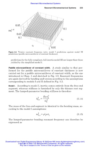
                              Figure 5.6 Torsion  resonant frequency ratio: model I predictions against model III
                              predictions (paddle microcantilever of constant thickness).

                                predictions by the fully compliant, full-inertia model III are larger than those
                                yielded by the simplified model I.

                              Paddle microcantilever of constant width. A study similar to that per-
                              formed for  the paddle microcantilever  of constant thickness is now
                              carried out for a paddle microcantilever of constant width, as the one
                              introduced in Chap. 3 and sketched in Fig. 3.9. Resonant frequencies
                              are again derived for bending and torsion according to the assumptions
                              corresponding to models I and II defined in Fig. 5.2.
                              Model I. According to model I, inertia comes entirely from the free-end
                              segment, whereas stiffness is furnished by only the thinner root seg-
                              ment. The lumped-parameter bending stiffness is therefore
                                                                3
                                                            Ewt 2
                                                       I
                                                      k b,e  =  3                        (5.14)
                                                             4l
                                                               2
                              The mass of the free-end segment is identical to the bending mass, ac-
                              cording to the model I assumptions:

                                                        I
                                                      m   = ȡl wt                        (5.15)
                                                        b,e   1  1
                              The lumped-parameter bending resonant frequency can therefore be
                              expressed as


                           Downloaded from Digital Engineering Library @ McGraw-Hill (www.digitalengineeringlibrary.com)
                                      Copyright © 2004 The McGraw-Hill Companies. All rights reserved.
                                        Any use is subject to the Terms of Use as given at the website.
   229   230   231   232   233   234   235   236   237   238   239