
Page 258 - Mechanical Engineers' Handbook (Volume 2)
P. 258
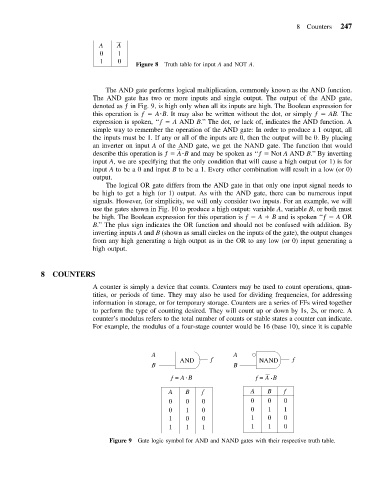
8 Counters   247


                             A    A
                             0    1
                             1    0
                                       Figure 8 Truth table for input A and NOT A.


                              The AND gate performs logical multiplication, commonly known as the AND function.
                           The AND gate has two or more inputs and single output. The output of the AND gate,
                           denoted as ƒ in Fig. 9, is high only when all its inputs are high. The Boolean expression for
                           this operation is ƒ   A B. It may also be written without the dot, or simply ƒ   AB. The
                           expression is spoken, ‘‘ƒ   A AND B.’’ The dot, or lack of, indicates the AND function. A
                           simple way to remember the operation of the AND gate: In order to produce a 1 output, all
                           the inputs must be 1. If any or all of the inputs are 0, then the output will be 0. By placing
                           an inverter on input A of the AND gate, we get the NAND gate. The function that would
                           describe this operation is ƒ   A  B and may be spoken as ‘‘ƒ   Not A AND B.’’ By inverting
                           input A, we are specifying that the only condition that will cause a high output (or 1) is for
                           input A to be a 0 and input B to be a 1. Every other combination will result in a low (or 0)
                           output.
                              The logical OR gate differs from the AND gate in that only one input signal needs to
                           be high to get a high (or 1) output. As with the AND gate, there can be numerous input
                           signals. However, for simplicity, we will only consider two inputs. For an example, we will
                           use the gates shown in Fig. 10 to produce a high output: variable A, variable B, or both must
                           be high. The Boolean expression for this operation is ƒ   A   B and is spoken ‘‘ƒ   A OR
                           B.’’ The plus sign indicates the OR function and should not be confused with addition. By
                           inverting inputs A and B (shown as small circles on the inputs of the gate), the output changes
                           from any high generating a high output as in the OR to any low (or 0) input generating a
                           high output.


            8   COUNTERS
                           A counter is simply a device that counts. Counters may be used to count operations, quan-
                           tities, or periods of time. They may also be used for dividing frequencies, for addressing
                           information in storage, or for temporary storage. Counters are a series of FFs wired together
                           to perform the type of counting desired. They will count up or down by 1s, 2s, or more. A
                           counter’s modulus refers to the total number of counts or stable states a counter can indicate.
                           For example, the modulus of a four-stage counter would be 16 (base 10), since it is capable


                                           A                      A
                                                   AND      f            NAND     f
                                           B                      B
                                                 f = A  B               f = A  B

                                                A    B   f             A   B    f
                                                0    0   0             0   0    0
                                                0    1   0             0   1    1
                                                1    0   0             1   0    0
                                                1    1   1             1   1    0
                               Figure 9 Gate logic symbol for AND and NAND gates with their respective truth table.