
Page 255 - Mechanical Engineers' Handbook (Volume 2)
P. 255
244 Digital Integrated Circuits: A Practical Application
position and remain there after the input is removed. Further inputs corresponding to down-
ward forces on this end will have no effect. Also, the state of the system can be described
by the position of either end, and if logical variables are introduced to designate these states,
the variables are complementary. The system exhibits the characteristics of memory in that
it remains in the state it has been set to with no further input.
The types of FFs used in digital equipment are identified by the inputs. They may have
from two up to five inputs depending on the type. They are all common in one respect in
that they have only two distinct output states. The outputs are normally labeled Q and Q
and should always be complementary. If Q 1, then Q 0, and vice versa. In this section,
the four types of FFs that are most common to digital equipment will be discussed and are
the D, R–S, T, and J–K FFs.
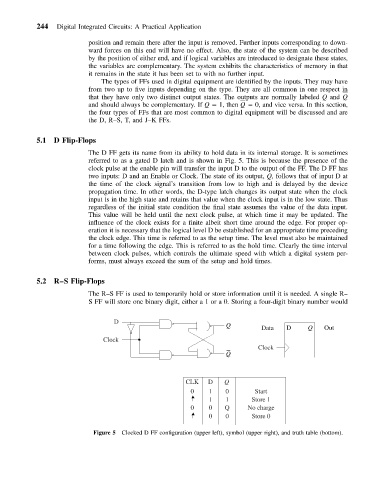
5.1 D Flip-Flops
The D FF gets its name from its ability to hold data in its internal storage. It is sometimes
referred to as a gated D latch and is shown in Fig. 5. This is because the presence of the
clock pulse at the enable pin will transfer the input D to the output of the FF. The D FF has
two inputs: D and an Enable or Clock. The state of its output, Q, follows that of input D at
the time of the clock signal’s transition from low to high and is delayed by the device
propagation time. In other words, the D-type latch changes its output state when the clock
input is in the high state and retains that value when the clock input is in the low state. Thus
regardless of the initial state condition the final state assumes the value of the data input.
This value will be held until the next clock pulse, at which time it may be updated. The
influence of the clock exists for a finite albeit short time around the edge. For proper op-
eration it is necessary that the logical level D be established for an appropriate time preceding
the clock edge. This time is referred to as the setup time. The level must also be maintained
for a time following the edge. This is referred to as the hold time. Clearly the time interval
between clock pulses, which controls the ultimate speed with which a digital system per-
forms, must always exceed the sum of the setup and hold times.
5.2 R–S Flip-Flops
The R–S FF is used to temporarily hold or store information until it is needed. A single R–
S FF will store one binary digit, either a 1 or a 0. Storing a four-digit binary number would
D
Q
Data D Q Out
Clock
Clock
Q
CLK D Q
0 1 0 Start
1 1 Store 1
0 0 Q No charge
0 0 Store 0
Figure 5 Clocked D FF configuration (upper left), symbol (upper right), and truth table (bottom).