
Page 256 - Mechanical Engineers' Handbook (Volume 2)
P. 256
5 Flip-Flops 245
require four R–S FFs. The name for the R–S FF is derived from the inputs, R for reset and
S for set, and is often referred to as an R–S latch. The R–S FF has two output conditions.
When the Q output is high and Q is low, the FF is set. When Q is low and Q is high, the
FF is reset. When the R and S inputs are low, the Q and Q outputs will both be HIGH.
When this condition exists, the FF is considered to be jammed and the outputs cannot be
used. The jammed condition is corrected when either S or R goes high. To set the FF requires
a high on the S input and a low on the R input. To reset, the opposite is required; S input
low and R input high. When both R and S are high, the FF will hold, or ‘‘latch,’’ the condition
that existed before both inputs went high.
In a complex digital system the signal levels are dynamic, and it is important to define
precisely the time at which transitions take place, thereby defining the time at which the
correct state is assumed. This is accomplished by issuing a clock pulse generated by an
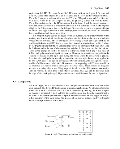
astable multivibrator to all FFs in the system. Such a configuration is shown in Fig. 6 where
the AND gates ensure that the set and reset logic levels are only applied at clock time. Here
the AND gates play the role of clock-controlled switches. In the absence of the clock signal,
shown as the triangle on the FF, the system is in the hold mode with S and R at a value of
0. The clock pulse may be of significant duration. However, these devices are typically fairly
sensitive to changes on the input lines during the period when the clock pulse is present.
Therefore, the clock pulse is normally shortened to a narrow spike before being applied to
the two AND gates. This can be accomplished by differentiating the clock pulse. The as-
sembly of differentiator and clocked FF constitutes an edge-triggered FF since transitions
are restricted to a narrow time at the edge of the clock pulse. These circuits are triggered
by either the rising edge or the falling edge of the clock pulse. This presents two device
states of concern: the state prior to the edge of the clock pulse (Q) and the new state after
the edge of the clock pulse (Q ). Figure 6 shows the possible states for this configuration.
5.3 T Flip-Flops
The T, or toggle, FF is a bistable device that changes state on command from a common
input terminal. The T-type FF is often used in counting applications. As with the other types
of FFs, the T FF is a derivative of the R–S FF. Comparatively speaking, the S and R inputs
are internally connected, R to Q and S to its complement, so that the only external input is
the clock. If an inverter precedes the T input, it indicates that the FF will toggle on a high-
to-low transition of the input pulse. The absence of an inverter indicates the FF will toggle
on a low-to-high transition of the pulse.
S R Q Q
0 0 0 0
Set S Q 0 0 1 1
0 1 0 0
Clock 0 1 1 0
1 0 0 1
Reset R Q 1 0 1 1
1 1 0 x
1 1 1 x
Figure 6 R–SFFconfiguration (left) and truth table (right).