
Page 257 - Mechanical Engineers' Handbook (Volume 2)
P. 257
246 Digital Integrated Circuits: A Practical Application
5.4 J–K Flip-Flops
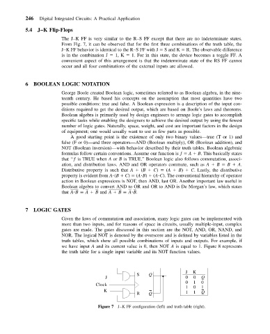
The J–K FF is very similar to the R–S FF except that there are no indeterminate states.
From Fig. 7, it can be observed that for the first three combinations of the truth table, the
J–K FF behavior is identical to the R–S FF with J S and K R. The observable difference
is in the combination J 1, K 1. For in this state, the device becomes a toggle FF. A
convenient aspect of this arrangement is that the indeterminate state of the RS FF cannot
occur and all four combinations of the external inputs are allowed.
6 BOOLEAN LOGIC NOTATION
George Boole created Boolean logic, sometimes referred to as Boolean algebra, in the nine-
teenth century. He based his concepts on the assumption that most quantities have two
possible conditions: true and false. A Boolean expression is a description of the input con-
ditions required to get the desired output, which are based on Boole’s laws and theorems.
Boolean algebra is primarily used by design engineers to arrange logic gates to accomplish
specific tasks while enabling the designers to achieve the desired output by using the fewest
number of logic gates. Naturally, space, weight, and cost are important factors in the design
of equipment; one would usually want to use as few parts as possible.
A good starting point is the existence of only two binary values—true (T or 1) and
false (F or 0)—and three operators—AND (Boolean multiply), OR (Boolean addition), and
NOT (Boolean inversion)—with behavior described by their truth tables. Boolean algebraic
formulas follow certain conventions. Assume our function is ƒ A B. This basically states
that ‘‘ƒ is TRUE when A or B is TRUE.’’ Boolean logic also follows commutation, associ-
ation, and distribution laws. AND and OR operators commute, such as A B B A.
Distributive property is such that A (B C) (A B) C. Lastly, the distributive
property is evident from A (B C) (A B) (A C). The conventional hierarchy of operator
action in Boolean expressions is NOT, then AND, last OR. Another important law useful in
Boolean algebra to convert AND to OR and OR to AND is De Morgan’s law, which states
that A B A B and A B A B.
7 LOGIC GATES
Given the laws of commutation and association, many logic gates can be implemented with
more than two inputs, and for reasons of space in circuits, usually multiple-input, complex
gates are made. The gates discussed in this section are the NOT, AND, OR, NAND, and
NOR. The logical NOT is denoted by the overscore and is defined by variables listed in the
truth tables, which show all possible combinations of inputs and outputs. For example, if
we have input A and its current value is 0, then NOT A is equal to 1. Figure 8 represents
the truth table for a single input variable and its NOT function values.
J K
S Q
J 0 0 Q
0 1 0
Clock
1 0 1
K 1 1 Q
R Q
Figure 7 J–KFFconfiguration (left) and truth table (right).