Page 259 - Mechanical Engineers' Handbook (Volume 2)
P. 259

248   Digital Integrated Circuits: A Practical Application


                                        A                      A
                                                 OR        f            NOR        f
                                        B                      B

                                               f = A + B             f = A + B

                                             A    B   f              A   B    f
                                             0    0   0              0   0    1
                                             0    1   1              0   1    1
                                             1    0   1              1   0    1
                                             1    1   1              1   1    0
                               Figure 10 Gate logic symbol for OR and NOR gates with their respective truth table.


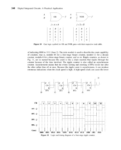
                          of indicating 0000 to 1111 (base 2). The term modulo is used to describe the count capability
                          of counters; that is, modulo-16 for a four-stage binary counter, modulo-11 for a decade
                          counter, modulo-8 for a three-stage binary counter, and so on. Ripple counters, as shown in
                          Fig. 11, are so named because the count is like a chain reaction that ripples through the
                          counter because of the time involved. The ripple counter is also called an asynchronous
                          counter. Asynchronous means that the events (setting and resetting of FFs) occur one after
                          the other rather than all at once. Because the ripple count is asynchronous, it can produce
                          erroneous indications when the clock speed is high. A high-speed clock can cause the lower


                                                                                        H

                                         Q  J        Q  J        Q   J        Q  J
                                          Clk         Clk         Clk          Clk
                                            K           K           K            K
                                          FF4         FF3         FF2          FF1
                                     D            C           B           A


                                 Q

                                 Q

                                 Q

                                 Q


                                     Figure 11 Logic and timing diagram of a four-stage ripple counter.
   254   255   256   257   258   259   260   261   262   263   264