
Page 317 - Mechanics of Asphalt Microstructure and Micromechanics
P. 317
Applications of Discrete Element Method 309
9.4.2.3 DEM Simulation Setup
3D
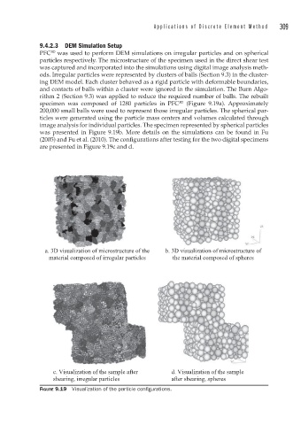
PFC was used to perform DEM simulations on irregular particles and on spherical
particles respectively. The microstructure of the specimen used in the direct shear test
was captured and incorporated into the simulations using digital image analysis meth-
ods. Irregular particles were represented by clusters of balls (Section 9.3) in the cluster-
ing DEM model. Each cluster behaved as a rigid particle with deformable boundaries,
and contacts of balls within a cluster were ignored in the simulation. The Burn Algo-
rithm 2 (Section 9.3) was applied to reduce the required number of balls. The rebuilt
3D
specimen was composed of 1280 particles in PFC (Figure 9.19a). Approximately
200,000 small balls were used to represent those irregular particles. The spherical par-
ticles were generated using the particle mass centers and volumes calculated through
image analysis for individual particles. The specimen represented by spherical particles
was presented in Figure 9.19b. More details on the simulations can be found in Fu
(2005) and Fu et al. (2010). The configurations after testing for the two digital specimens
are presented in Figure 9.19c and d.
a. 3D visualization of microstructure of the b. 3D visualization of microstructure of
material composed of irregular particles the material composed of spheres
c. Visualization of the sample after d. Visualization of the sample
shearing, irregular particles after shearing, spheres
FIGURE 9.19 Visualization of the particle confi gurations.