
Page 312 - Mechanics of Asphalt Microstructure and Micromechanics
P. 312
304 Ch a p t e r N i n e
Macro-Strain
No. d x d y d z d xy d yz d xz
1 0.00 –0.05 –0.05 –0.04 0.02 –0.04
2 0.70 –1.10 –0.80 –0.43 –0.08 –0.97
3 0.07 –0.08 0.00 0.10 0.11 0.30
4 –0.14 0.03 3.35 0.15 0.33 –0.42
5 0.17 –0.26 –0.04 0.10 0.05 –0.09
6 0.02 0.12 –0.21 0.05 0.09 –0.05
7 0.01 0.03 –0.09 –0.01 0.05 –0.04
8 0.20 0.07 0.02 0.00 0.14 –0.03
9 –0.04 0.07 0.45 –0.04 0.03 –0.16
10 2.32 –1.03 –0.14 –2.11 –1.19 2.58
TABLE 9.6 Local macro-strains from experimental measurements (in 10 tetrahedrons).
3D
9.4.1.7 PFC and DEM Simulation
The PFC was used for simulating the above test in order to investigate the particle
3D
shape effect on the micro-macro behavior of granular materials. It was used to conduct
DEM simulation on irregular particles and on spherical particles, respectively. The ac-
tual microstructure used in the confined compression test was incorporated into the
simulation. Irregular particles were represented by clusters of balls. Each cluster be-
3D
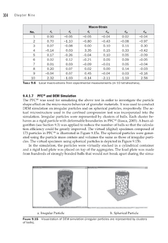
haves as a rigid particle with deformable boundaries in PFC (Itasca, 2005). A burn al-
gorithm (see Section 9.3) was applied to reduce the number of balls so that the calcula-
tion efficiency could be greatly improved. The virtual (digital) specimen composed of
173 particles in PFC is illustrated in Figure 9.15a. The spherical particles were gener-
3D
ated using the particle mass centers and volumes the same as those of irregular parti-
cles. The virtual specimen using spherical particles is depicted in Figure 9.15b.
In the simulation, the particles were virtually stacked in a cylindrical container
and a rigid load plate was placed on top of the aggregates. The load plate was made
from hundreds of strongly bonded balls that would not break apart during the simu-
a. Irregular Particle b. Spherical Particle
FIGURE 9.15 Visualization of DEM simulation (irregular particles are represented by clusters
of balls).