
Page 145 - Mechanics of Microelectromechanical Systems
P. 145
132 Chapter 3
doing so, the beam elastically deforms mainly under bending or/and torsion.
Figures 3.1 and 3.2 illustrate two microaccelerometer configurations that are
supported by two identical beams (Fig. 3.1) and by four identical beams (Fig.
3.2), respectively. Each beam is fixed at one end by means of an anchor.
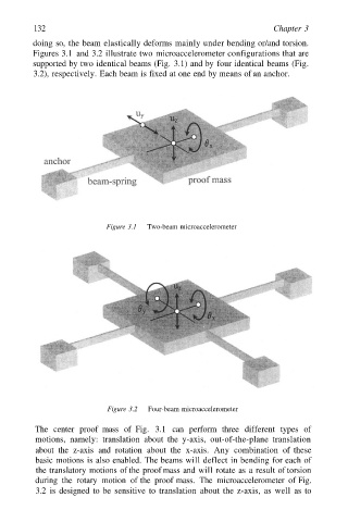
Figure 3.1 Two-beam microaccelerometer
Figure 3.2 Four-beam microaccelerometer
The center proof mass of Fig. 3.1 can perform three different types of
motions, namely: translation about the y-axis, out-of-the-plane translation
about the z-axis and rotation about the x-axis. Any combination of these
basic motions is also enabled. The beams will deflect in bending for each of
the translatory motions of the proof mass and will rotate as a result of torsion
during the rotary motion of the proof mass. The microaccelerometer of Fig.
3.2 is designed to be sensitive to translation about the z-axis, as well as to